http://sphotos-c.ak.fbcdn.net/hphotos-ak-ash4/407695_4880626299016_1734733296_n.jpg
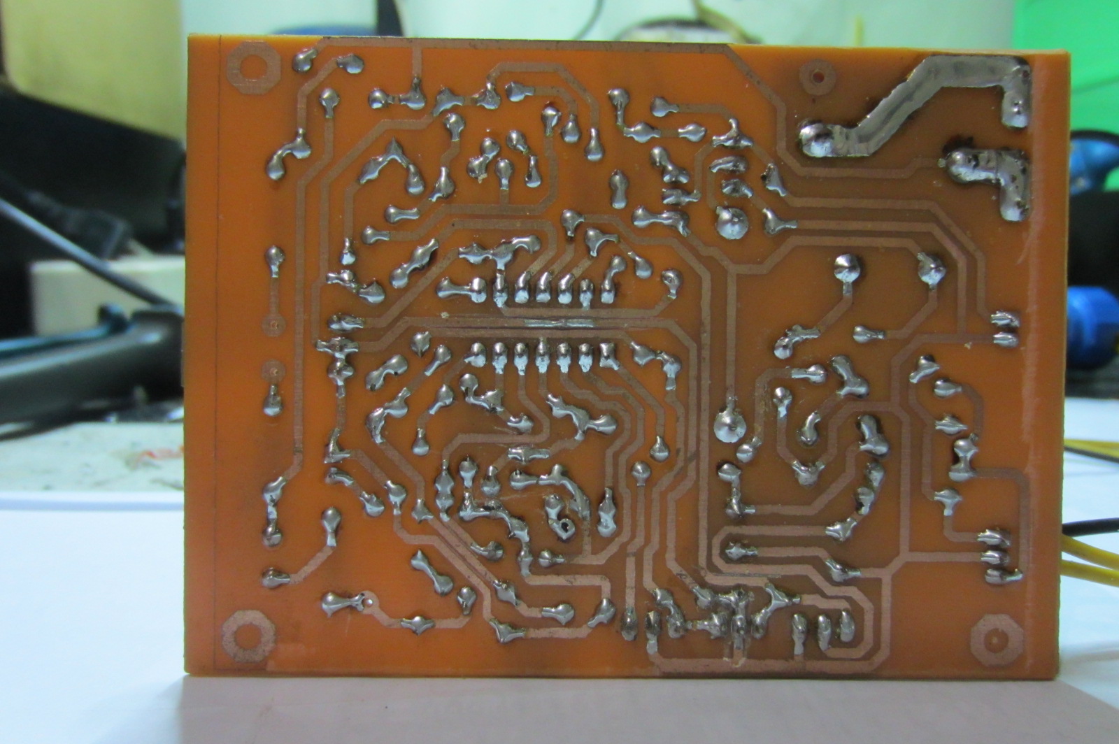
finally finished also protect the speakers that I created using APEX design, thanks Mr.Mile has given a good component layout, I just change the model of the relay without any change. relay works fine. IC 7912 and R 5W 47R hot, is there a problem? beg the help sir.
IC 7912 and resistor 47R/5W are used for fan suply... post pictures with botom side of your pcb.
Maybe this would help?
hi sir apex can I use a tranformer with 45-45-0-45-45 VAC with 4 pairs of output transistor in this type of clas h-amp? I tried this h-amp using 30-30-0-30-30 VAC with out problem and sounds great to my ears so I want it for more power.
Thanks in advance
IC 7912 and resistor 47R/5W are used for fan suply... post pictures with botom side of your pcb.
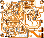
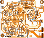
This image is not updated, only the addition of paths in the relay coil to the diode
diyAudio
http://www.diyaudio.com/forums/atta...6308-900w-h-class-pa-amp-limiter-img_0371.jpg
Last edited:
measure the voltage across that 5W 47R resistor and than calculate power disipated on it by the formula P=R x I^2. if the power calculated is larger than 2W than you should use 7W resistor.
power disipated by 7812 is also easy calculated by measuring voltage between in/out pinouts and multiplying it with current flowing through it. if the power calculated is smaller than suggested by manufacturer than just add a heatsink on it.
.
what voltage is at relay coil?
.
what is main supply voltage?
Coil Relay 24VDC
IC 7912 and resistor 47R/5W are used for fan suply... post pictures with botom side of your pcb.
Sir MILE, Here Layout PCB Protect
Attachments
i was commenting from bus on my way home and did not have schematics to see so i thought that it supplies the relay coil. anyway,power disipated by 5W resistor and voltage regulator is to be calculated as i said and than decide will you replace the resistor and put the heatsink od voltage regulator,wich i would anyway. greetings!
i was commenting from bus on my way home and did not have schematics to see so i thought that it supplies the relay coil. anyway,power disipated by 5W resistor and voltage regulator is to be calculated as i said and than decide will you replace the resistor and put the heatsink od voltage regulator,wich i would anyway. greetings!
OK, thanks for the advice. I hope Mr. APEX can provide input for this. problems in R 5 Watt and IC 7912 are very hot.
Last edited:
OK, thanks for the advice. I hope Mr. APEX can provide input for this. problems in R 5 Watt and IC 7912 are very hot.
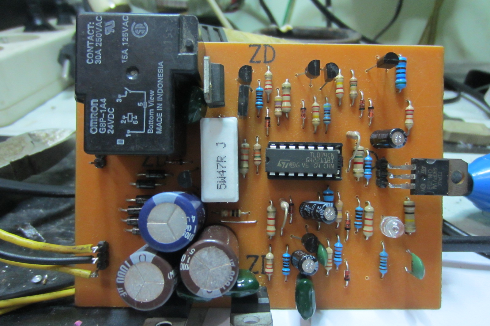
Replace IC 7912, without fan connected to pcb IC and 5W resistor must be cold. With connected fan only resistor 47R/5W can be warm.
Replace IC 7912, without fan connected to pcb IC and 5W resistor must be cold. With connected fan only resistor 47R/5W can be warm.
I have yet to install the fan into the relay module test only can work or not, after I check the IC 7912 and R 5 Watt hot, with no load (Fan)
I have yet to install the fan into the relay module test only can work or not, after I check the IC 7912 and R 5 Watt hot, with no load (Fan)
Check your layout. there is missing link on 1N4148 to supply +24
I have yet to install the fan into the relay module test only can work or not, after I check the IC 7912 and R 5 Watt hot, with no load (Fan)
Please see attach picture!
Attachments
Please see attach picture!
Post #2305 shown it's been rectified.... now he has heat issue with 47R/5W and IC 7912.
Damanhuri, My protect it only get warm this two component having the fan connected, if the fan is disconnected they must be cold.
Regards,
Post #2305 shown it's been rectified.... now he has heat issue with 47R/5W and IC 7912.
Damanhuri, My protect it only get warm this two component having the fan connected, if the fan is disconnected they must be cold.
Regards,
I'll try to replace the 7912 IC tomorrow
Hello Mile sir,
Having built B500 I m impressed by the performance of the amp. The next step is to get the most juice out of my 2.5kva toroid and 2kw speakers.. I have gone through this thread and finally decided to built H900. What I couldn't find is H900 schematic with 8pairs of output transistors to support 2ohms and 16 ohm loads. Maybe I have missed it. So I am looking for H900 triple emitter follower schematic/circuit . I request Mile sir or diy members to please help me with H900 tef circuit. Thank you 🙂
Having built B500 I m impressed by the performance of the amp. The next step is to get the most juice out of my 2.5kva toroid and 2kw speakers.. I have gone through this thread and finally decided to built H900. What I couldn't find is H900 schematic with 8pairs of output transistors to support 2ohms and 16 ohm loads. Maybe I have missed it. So I am looking for H900 triple emitter follower schematic/circuit . I request Mile sir or diy members to please help me with H900 tef circuit. Thank you 🙂
H900 truelly diyers
Happy holliday to all...
This forum is verry helpfull. Specially thanks to mr mille...
Your dsign is unic n naturally but expert.... 😉
good job sir...
Nice..
[image][/image]
Happy holliday to all...
This forum is verry helpfull. Specially thanks to mr mille...
Your dsign is unic n naturally but expert.... 😉
good job sir...
Nice..
[image][/image]
Attachments

Last edited:
Hi mr. Damanhuri.... have u finish make protect?... share that for diy...
nice project
there are constraints on the regulator Fan. I would replace the 7912 IC
Post #2305 shown it's been rectified.... now he has heat issue with 47R/5W and IC 7912.
Damanhuri, My protect it only get warm this two component having the fan connected, if the fan is disconnected they must be cold.
Regards,
Thanks for reply. Damanhuri, pls check the reisistance of your IC7912 and 47R/5W.
Happy holliday to all...
This forum is verry helpfull. Specially thanks to mr mille...
Your dsign is unic n naturally but expert.... 😉
good job sir...
Nice..
[image][/image]
Thanks,
Regards
- Home
- Amplifiers
- Solid State
- 900W H-class PA Amp with Limiter