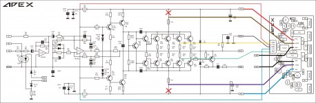
![APEX%20B500%20SCH[1].jpg](/community/data/attachments/159/159723-0736348816dc2bf97eba5c3f1bd97346.jpg?hash=BzY0iBbcK_)
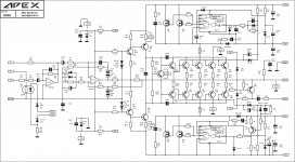
![APEX%20Hclass%20Power%20DriverMON[1].jpg](/community/data/attachments/159/159737-e4758819b6a6fbb23f402828618b49e2.jpg?hash=5HWIGbam-7)
b500+tl072 stepapex,
please help me figure out how to use tlo step driver to b500
Attachments
apex,
in h900 MV+ MV- going to fuse,
here MV+ MV-no connection?
0VD+ 0VD-going to fuse
regards
MV medium voltage
HV high voltage
what is 0Vd? 0 volt_____?
in h900 MV+ MV- going to fuse,
here MV+ MV-no connection?
0VD+ 0VD-going to fuse
regards
MV medium voltage
HV high voltage
what is 0Vd? 0 volt_____?
OVD is output from H-class step driver, and there is MV or HV when mosfets off/on, that output going to fuse, same as H900 with different step driver. In H900 MV going to comutation diode not to fuse.apex,
in h900 MV+ MV- going to fuse,
here MV+ MV-no connection?
0VD+ 0VD-going to fuse
regards
MV medium voltage
HV high voltage
what is 0Vd? 0 volt_____?
Last edited:
apex,
how about psu post #131
😀i'm into confusion with this MV+ MV- post#402 please enlighten me apex
regards
how about psu post #131
😀i'm into confusion with this MV+ MV- post#402 please enlighten me apex
regards
PSU post #131 will be OK.apex,
how about psu post #131
😀i'm into confusion with this MV+ MV- post#402 please enlighten me apex
regards
To long for thread, I suggest U to learn about basic princip of H-class for understandig this project.
Regards
H900 is 900W 4R, 500W 8R. (1500W 2R not recomended)hi Apex, the Amplifier H900 is 900W in 8R ? Work in 4R or 2R ?
Thank you.
Regards
Hi Apex,
Per your schematic in post #402 +HV -HV goes to amp should it not go to the PS together with the +MV & -MV only the 0VD should go to the amp as the HV & MV should appear on it as it is switch by the controller.
Rey
Per your schematic in post #402 +HV -HV goes to amp should it not go to the PS together with the +MV & -MV only the 0VD should go to the amp as the HV & MV should appear on it as it is switch by the controller.
Rey
Hi Apex,
Per your schematic in post #402 +HV -HV goes to amp should it not go to the PS together with the +MV & -MV only the 0VD should go to the amp as the HV & MV should appear on it as it is switch by the controller.
Rey
From PSU goes HV and MV. HV goes together on step and to amp for supply VAS. OVD goes to output stage, which is disconeted from HV. MV goes only to step driver.
Last edited:
From PSU goes HV and MV. HV goes together on step and to amp for supply VAS. OVD goes to output stage, which is disconeted from HV. MV goes only to step driver.
Thanks.
Rey
Yes H-class 4x55V,four pairs output transistors, TO220 mosfets in step driver... that's becomes standard in modern PA amplifiers.
BF422/BF423 pins E C B >bf422/bf423 any replacement?
MPSA42/MPSA92 pins E B C
This is 10years old schematics. Can be upgrade with new OP amp.

First PA amplifiers schematics B250 and H750 useing TL072, and lete B500 and H900 useing NE5532, but I think for this PA amplifier that is good enough.
Apex, resistance R27 ( 22R ) must be placed close to 15033 / 15032 , or can be placed in the PCB's stepdrive side
Yes, can be placed on step side, and I suggest use two 12R in serial instead one 22R.Apex, resistance R27 ( 22R ) must be placed close to 15033 / 15032 , or can be placed in the PCB's stepdrive side
Regards
Last edited:
- Home
- Amplifiers
- Solid State
- 900W H-class PA Amp with Limiter