If you jerk the rails around on EMITTER FOLLOWERS they don't usually do anything stupid. The amps can be made quite stable.
Yes that is correct HOWEVER the last GAIN STAGE is included to achieve the higher voltage in all the common designs I have even seen.
You have hit on a very curious idea in having the drive stage (or last gain stage) always operate on the higher voltage and let the emitter follower stage (stages) have the voltage rail jerked around. I could see this work actually! As you correctly say as an emitter follower the supply voltage means almost nothing. KUDOS. Unfortunately not one amp I have seen is built this way. Maybe it is time for a sensible rail voltage jerking amp. 200 volt drive stage and a rail voltage jerking output emitter follower stage only. GREAT idea!
Someone actually had an original thought, WOW. I will drink to that!😎
Unfortunately, not original. I have a whole rack full of Crest CA18's that are built that way. I've built two of my own, and working on a more-or-less "production" design that all use rail switched EFs. Triples, actually. And they are stable.
An old prototype used an all NPN output stage so I could use up a bunch of 2N3773's that were laying around. Couldn't make it stable to save my soul. Got mad, ripped out the negative bank and jumpered the PCB to take PNPs. Worked the first time.
An old prototype used an all NPN output stage so I could use up a bunch of 2N3773's that were laying around. Couldn't make it stable to save my soul. Got mad, ripped out the negative bank and jumpered the PCB to take PNPs. Worked the first time.
DIY first and great idea!
The more I consider this the more it seems like a truly righteous idea!
Now the bad news- how are the absolutely required reverse kickback diodes installed? Simply backward across the output emitter follower stage...hummm. Yes that might work also. The reverse kickback diodes must be in any competent design or POOF go the output transistors.
Okay I will bite. I got a boat load of APEX (now cirrus semi) 300 volt hybrid op-amps, PA08A, that beg for this NEW design. Will sketch it up using ±75 and ±150 volt rails. FYI- I have so many of these PA08A if anyone want to purchase one or some for less than ½ price let me know.
You saw it here first folks and anyone who goes and tries to patent this will be taken to task. Rail voltage jerking amps that don't smoke and do make a certain sense... a DIYaudio invention!! What could be better?
All, this is why I joined DIY- to get a REAL idea. Thanks to APEXAUDIO and everyone else too!
Unfortunately, not original. I have a whole rack full of Crest CA18's that are built that way. I've built two of my own, and working on a more-or-less "production" design that all use rail switched EFs. Triples, actually. And they are stable.
An old prototype used an all NPN output stage so I could use up a bunch of 2N3773's that were laying around. Couldn't make it stable to save my soul. Got mad, ripped out the negative bank and jumpered the PCB to take PNPs. Worked the first time.
OH.

So that begs the question- Why are all these other incredibly stupid designs around when such a good one is available?
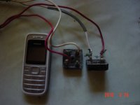
This soft-start circuit will be OK.can i use quasi's slow turn on/soft satrt ckt
Slow turn cct (Quasi's DIY Audio Site)
Go Advancedhow to attached picture here,
i have big torroid
i want you to see it if fits h 900
Manage Attachments
Browse (find pic on your hard)
Upload...
In post #107 U can find H-class driver.The more I consider this the more it seems like a truly righteous idea!
Now the bad news- how are the absolutely required reverse kickback diodes installed? Simply backward across the output emitter follower stage...hummm. Yes that might work also. The reverse kickback diodes must be in any competent design or POOF go the output transistors.
Okay I will bite. I got a boat load of APEX (now cirrus semi) 300 volt hybrid op-amps, PA08A, that beg for this NEW design. Will sketch it up using ±75 and ±150 volt rails. FYI- I have so many of these PA08A if anyone want to purchase one or some for less than ½ price let me know.
You saw it here first folks and anyone who goes and tries to patent this will be taken to task. Rail voltage jerking amps that don't smoke and do make a certain sense... a DIYaudio invention!! What could be better?
All, this is why I joined DIY- to get a REAL idea. Thanks to APEXAUDIO and everyone else too!
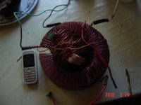
Will be OK, QSC RMX-2450 or Behringer EP-2500 use even smaller.can this torroid meet the 2500kva requirement?
see cell phone for torroid size
35A bridge also can be used.maybe this bridge diode is enough
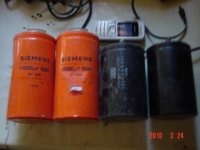
This old caps U can save for some amp in AB class.this reservoir must be replace,
thanks to apex for smaller pcb design,
i can now use more compact casing,
smaller caps would be better,
casing height is reduced
though still heavy
if compact smps with 4x40v
that would be great
casing height is reduced
though still heavy
if compact smps with 4x40v
that would be great
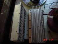
Heatsinks are OK, with two 24V fan cooler (front/back push-pull)how about this heatsink?
is this enough?
Heatsinks are OK, with two 24V fan cooler (front/back push-pull)
which is better
if i use 24v supply
transformer must have 4x40v +/-15, and another 24v for the fan
if i use another small x-former for fan and protect circuit
what is the desired ampere
- Home
- Amplifiers
- Solid State
- 900W H-class PA Amp with Limiter