i do this for testing Mr gantex
1. I use 1 transformer with 45 40 0 40 45 Vac with 10000/80V capasitor
2. i use 2 trafo with each secondary 42 0 42 and 45 0 45 but one of the diode got hot, i think this fail or one of my transformer broken (old transformer) with same 10000/80V capasitor
3. now i testing with toroid transformer 45 32 0 32 45 Vac with 8 6800/63V capasitor and 2 fake 35A fake motorola diode 😀 n the result is like this picture are this normal?
i'm finishing build H900 in december but i power up H900 this week 😀
i'm very courious to build this psu, may be my multimeter got broken too, cause several days ago i got wrong measurement
So what trafo u use now. nothing wrong with scheme. but, are u sure 32vac get 45vdc?
where diode goest hot at the pic u upload? are u check this diode with multitester?
Last edited:
DC voltage = 1,414 * AC voltage (Diode bridge forward voltage don't count, no load condition).
If you have 45 32 0 32 45 trafo, you must have aprox. +63 +45 0 -45 -63 dc voltage. You can not change the physic of law 😀.
Please measure all voltage with ground as reference. If you measure DC voltage, set the multimeter for DC voltage and if you measure AC voltage, set the multimeter for AC voltage.
than that's correct i get approx +60 +45 0 -45 -60 VDC cause i use analog multimeter can't see like digital and yes i test with ground reference with correct setting multimeter and the result as picture also without load, thanks mr. bimo
So what trafo u use now. nothing wrong with scheme. but, are u sure 32vac get 45vdc?
where diode goest hot at the pic u upload? are u check this diode with multitester?
i use only 1 toroid transformer right now with 45 32 0 32 45 Vac for testing like the picture i upload, the diode get hot when last week i use 2 transformer combine 10A toroid and 10A regular transformer 😀 for testing, i have 3 toroid n 1 regular transformer from my old amplifier for testing, but never try combine 2 toroid transformer, there is nothing wrong with the sceme but the result in my testing make me confuse😕 😀, build H900 with less problem but get problem when built it psu 😀
Last edited:
than that's correct i get approx +60 +45 0 -45 -60 VDC cause i use analog multimeter can't see like digital and yes i test with ground reference with correct setting multimeter and the result as picture also without load, thanks mr. bimo
i use only 1 toroid transformer right now with 45 32 0 32 45 Vac for testing like the picture i upload, the diode get hot when last week i use 2 transformer combine 10A toroid and 10A regular transformer 😀 for testing, i have 3 toroid n 1 regular transformer from my old amplifier for testing, but never try combine 2 toroid transformer, there is nothing wrong with the sceme but the result in my testing make me confuse😕 😀, build H900 with less problem but get problem when built it psu 😀
why confuse?
if your result same as the picture. i think anything is rite. or u can try use another multitester just to make sure psu are correct.


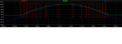
Class TD/Eeengine amplifier under simulation.
Blue trace is the output signal
Green is the supply voltage of the output devices
Red is the output of the class D output voltage.
Sajti
😎

This is new class of an amplifier? Can you share your simulation file?
😎
This is new class of an amplifier? Can you share your simulation file?
Not a really new, and it was developed to get the highest possible power with the highest possible efficiency.
I will post the asc file as I will finish the planning. It's working quite good up to 5kHz only.
Sajti
Not a really new, and it was developed to get the highest possible power with the highest possible efficiency.
I will post the asc file as I will finish the planning. It's working quite good up to 5kHz only.
Sajti
If it can have low enough distortion, may be less than 0,1%, never mind it can only work up to 5kHz. It can be use sub-woofer amp.
The share of high-frequency components in the real signal is small, so the envelope is formed mainly low and middle frequencies. High frequencies are well practiced G-class tracker, which is an ancillary element.
We worked at a club with such a device, the sound was good.
We worked at a club with such a device, the sound was good.
If it can have low enough distortion, may be less than 0,1%, never mind it can only work up to 5kHz. It can be use sub-woofer amp.
It gives about 1200W/4ohm with about 0.009% distortion, using +/-120V supply voltage.
Of course this is just a simulation, but I plan to build some...
Sajti
The share of high-frequency components in the real signal is small, so the envelope is formed mainly low and middle frequencies. High frequencies are well practiced G-class tracker, which is an ancillary element.
We worked at a club with such a device, the sound was good.
The HF drivers need not too much power, so we can use class AB, of modulated rail class H for the HF.
Sajti
Agree.The HF drivers need not too much power
Sajti
we used the one power amp for the entire band - wideband acoustics.
It gives about 1200W/4ohm with about 0.009% distortion, using +/-120V supply voltage.
Of course this is just a simulation, but I plan to build some...
Sajti
0.009% ? 😎
Is the principle of power supply modulation like class AA amplifier from technics?
update with my h900 adding 1 transformer 15amps each channel..
and pls. help. how much power that i can get in 8ohms load using 80-40-0-40-80 ac 15amps
http://postimg.org/image/h7bzuqvw7/
View image: DSC 0784
View image: DSC 0785
and pls. help. how much power that i can get in 8ohms load using 80-40-0-40-80 ac 15amps
http://postimg.org/image/h7bzuqvw7/
An externally hosted image should be here but it was not working when we last tested it.
View image: DSC 0784
An externally hosted image should be here but it was not working when we last tested it.
View image: DSC 0785
An externally hosted image should be here but it was not working when we last tested it.
Last edited:
nice build.
around 400 watts per channel... but i have some doubts of your taffo power handling. it has very little or no headroom for 2 channels at full power. if you can use two of them, one for each channel, the better.
around 400 watts per channel... but i have some doubts of your taffo power handling. it has very little or no headroom for 2 channels at full power. if you can use two of them, one for each channel, the better.
0.009% ? 😎
Is the principle of power supply modulation like class AA amplifier from technics?
I don't think. The amp did same performance with modulated rail class H, but using about 12 pairs output devices.
Sajti
nice build.
around 400 watts per channel... but i have some doubts of your taffo power handling. it has very little or no headroom for 2 channels at full power. if you can use two of them, one for each channel, the better.
Thanks sir jaagut...
Hi Sandman15th,
I saw from your photo you use 4.7k 5watt instead of 2.2k near emitter resistor? whats the different in using 2.2k?
I saw from your photo you use 4.7k 5watt instead of 2.2k near emitter resistor? whats the different in using 2.2k?
Hi Sandman15th,
I saw from your photo you use 4.7k 5watt instead of 2.2k near emitter resistor? whats the different in using 2.2k?
hi, its depend on your supply mv voltage same like in b500 i used 5watts instead of 2watts .. R24 R25 summary
+/-40v dc 1k2 2w
+/-55 1k5
+/-80 2k2
+/-90v dc 4k7 2w
Last edited:
hi, its depend on your supply mv voltage same like in b500 i used 5watts instead of 2watts .. R24 R25 summary
+/-40v dc 1k2 2w
+/-55 1k5
+/-80 2k2
+/-90v dc 4k7 2w
Maybe u mean HV rite? ur MV is 40vdc.
- Home
- Amplifiers
- Solid State
- 900W H-class PA Amp with Limiter