Without half of NE5532 summary gain of amp will be not enouth for standart 0, 775V 0dB.
OK Understood. But You can increase the gain of the input opamp, or even the OPA134.
Sajti
standart 0, 775V 0dB.
Anyway I found that there is a new standard, which is 32dB (40x) gain. This helps if You use different amps for the low/mid/high. Most of the manufacturer using this.
Sajti
I have long used and generally accepted standards to nominal output power was obtained when applying the standardized signal level.
Increasing a gain of OPA134 will increase distortion.But You can increase the gain of the input opamp, or even the OPA134.
Do you have no access to Farnell.com, and other? In every internet shop you can buy it.
ok thanks for the answer and its support greetings 🙂 🙂 🙂
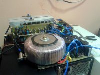
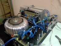
3rd amplifier at a finish line 🙂 Power transformer same as QSC RMX2450 and previous. Power module, protection and channels.
Attachments
Last edited:
Hi Andrew!
I can post a voltage-controlled amplifier only. For gain control details please see a datasheet of LM13600 (or LM13700)

I can post a voltage-controlled amplifier only. For gain control details please see a datasheet of LM13600 (or LM13700)
Last edited:
3rd amplifier at a finish line 🙂 Power transformer same as QSC RMX2450 and previous. Power module, protection and channels.
Looks nice. Anyway, what kind of heatsink are You use?
Sajti
sajti, i use a AB0096 with parallel tunnel airflow. For full view please see post 5.
I checked the pdf. Nice heatsink. My idea is on the attached picture.
Sajti
Attachments
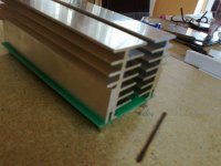
Very nice! I would not abandon such radiators, if they were we have for sale.
One problem: this profiles cannot be used for amplifiers with 4 or more pairs TO264 output transistors. Because you need to place at the heatsink not only output stage. Drivers, pre-drivers, diodes, voltage amplifier output stage, etc. - that's all is a hot parts. Therefore, for high power amplifiers profitable double-row arrangement of transistors, called "butterfly". In addition, this arrangement minimizes the power circuits of the output stage. It is this construction I prefer to use.
One problem: this profiles cannot be used for amplifiers with 4 or more pairs TO264 output transistors. Because you need to place at the heatsink not only output stage. Drivers, pre-drivers, diodes, voltage amplifier output stage, etc. - that's all is a hot parts. Therefore, for high power amplifiers profitable double-row arrangement of transistors, called "butterfly". In addition, this arrangement minimizes the power circuits of the output stage. It is this construction I prefer to use.
Last edited:
Very nice! I would not abandon such radiators, if they were we have for sale.
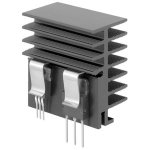
Yes. They are available from Fischer. Check for SK514. My plan is to not use any insulator between the output devices and the heatsink. So the heatsinks are act as power supply rails too...
Sajti
PS.: The pictures show arrangement for single channel only!
Your idea is not entirely successful. I would have done differently: under the output transistors would put tires made of aluminum or copper strips with a thickness of 5...10 mm, tires would be insulated from the heat sinks and transistors fastened directly to the tires. The point is that noise from the output stage is not emanated would sink to the input circuit of the amplifier. In this case, the radiators can be grounded on the body of the device.So the heatsinks are act as power supply rails too...
Ok, that alters the case 🙂 But the radiator is still better to ground.PS.: The pictures show arrangement for single channel only!
PS. I completely forgot about the existence of ceramic pads for transistors. No additional tires do not need, if you remember the conductivity of this pottery.
Last edited:
Your idea is not entirely successful. I would have done differently: under the output transistors would put tires made of aluminum or copper strips with a thickness of 5...10 mm, tires would be insulated from the heat sinks and transistors fastened directly to the tires. The point is that noise from the output stage is not emanated would sink to the input circuit of the amplifier. In this case, the radiators can be grounded on the body of the device.
Ok, that alters the case 🙂 But the radiator is still better to ground.
I understand Your solution. However the missing insulators let me to use smaller heatsink, because of the better thermal coupling. The PSU noise is not issue with class AB (smaller power up to 500W/4ohm), and for higher power I will try to use modulated rail class H.
Sajti
aluminum or copper strips with a thickness of 5...10 mm, tires would be insulated from the heat sinks and transistors fastened directly to the tires.
I'm not able to use this solution with this heatsink as I will fix the devices as You can see on the attached picture. It's very comfortable...
Sajti
Attachments
For AB-class you are right. On H-class switching floors gives a big hindrance with significant high frequency.The PSU noise is not issue with class AB (smaller power up to 500W/4ohm), and for higher power I will try to use modulated rail class H.
Sajti
I did an experiment: on the radiator housed the output stage and the radiator was not grounded. On the oscilloscope was visible interference from switching floors. After grounding the heat sink obstacle completely disappeared. On the website, where I showed waveforms, was given the first case, for clarity and awareness of the need of a competent design. Therefore, if the radiator is not grounded, it will be accompanied by a sharp increase in the higher order distortion at the beginning of the connection of the second floor.
On the website, where I showed waveforms, was given the first case, for clarity and awareness of the need of a competent design.
Do You mean the russian forum? I will check it, even I not speak russian very well 🙂
Sajti
I understand.
Images with switching interferences. Or direct link - http://forum.cxem.net/index.php?showtopic=111627&#entry1480784


Images with switching interferences. Or direct link - http://forum.cxem.net/index.php?showtopic=111627&#entry1480784
- Home
- Amplifiers
- Solid State
- 900W Class H Power Amplifier