Hi Michael
I apologize, I made a big mistake in trafo models.
When I read that the primary inductance was,
for example, 150H, I put each half primary at 75 H.
This is not correct. It works for resistance but not for inductance.
One has to divide by four not by two, because inductance
is proportional to N^2. One may think that if one choke has
and inductance of 10H then two chokes in series have and inductance of 20H and this is correct because the two core
are separeted. But if they are on the same core, i.e. they are coupled, then the inductance will be 40H. As in trasformers.
So, please divide by two the inductance values
of each half primary and half secondary.
Ciao
Federico
transformer models
OK Federico, I changed all the inductances in the 1620 file to half and the large inductances in the 1660S file. A quick glance at the transient analysis seems to show an increase in 3rd harmonic, but a decrease in 5th and 7th. Maybe I have changed something else too in the meantime. Just noticed that I now a 10VCDC imbalance that shows up between the two halves of the primary (in the model). Will have to check further.
After some problems getting my grounding all hooked up and one B+ power supply quitting (I don't think it was anything I did) I got the output stage running. I haven't connected the front end yet. It seems to pass more current than the model suggests. If I measured correctly I am seeing 77mA/tube with a bias of -89.5 and a B+ of 682VDC.
Definitely a winter time amp.
Michael
Noise
OK! it makes noise. Even after a manner plays music. Lots of hum and crap noise though. I will have to do a thorough check of my grounds on the input transformer and a general once over of the circuit altogether and see if I can quiet it down a bit. As you might imagine with 5 separate power supplies some time might be spent sniffing out the proper circuit connections and filter schemes.
Michael
Wow
a good work
I think that at this prototyping stage it is easy to
get noise from some place around.
How much have you paid for the 845s?
The inductance to change in the models are all and only
those cited in the K (core) element(double click on it).
thus the leakage inductance values are not to be changed.
I'll go to Croazia (ex Jugoslavia) these holydays
see you later
ciao
Federico
tubes etc
I paid $80/matched pair from triode electronics for the 845.
Oops, I changed the leakage too. Will have to redo.
Have fun in Croatia, hopefully I will have some better results when you return.
Michael
I paid $80/matched pair from triode electronics for the 845.
Oops, I changed the leakage too. Will have to redo.
Have fun in Croatia, hopefully I will have some better results when you return.
Michael
up and running
Well, one channel is up and running. Still quite a few things to figure out though. Have gotten rid of the hashy noise, but now the 60Hz hum is worse. Somehow it is coming from the front end. If I turn the front end off I can null the hum down to ~10mV p-p. When I turn the front end on it jumps up to ~100mV. Fortunately, I am doing my testing with some less efficient speakers, so it is quite tolerable. Also had some anomalies with the 6SN7-12B4 combo. When I would power up the 6SN7 the 12B4 would quit conducting. Never did figure out what was causing that.
Haven't tried implementing the dynamic balance circuit yet. Will work on that after I am sure everything else is operating as it should be and I lose my fear of it running away or something. It does sound very good already. Have only done a preliminary distortion survery and it is quite low at lower outputs but goes up a lot after ~20W. Max power at the moment seems to be 40W.
Lots of fun stuff ahead, eh?
Michael
A2 troubles
Hi All,
Hum problem is gone, mostly at least. A new question though, when the amp passes into the positive grid region it starts rebiasing itself more negative. I had the output stage setup more or less as drawn in post 67 of this thread. At somewhere between 15 and 17 watts output the grid would start becoming more negative with increase in applied signal. I thought it might be the rectified signal was causing the drop due to the large resistances in the setup, so I built a new variable negative power supply that contains no resistances other than a 300R choke in the ground leg. It is even worse, reaching -150V from a setpoint of -85. Nice safety feature, but I don't think it would sound to good judging from the major crossover distortion I see on the scope. Anyone have any ideas on what's up?
Thanks,
Michael
Hi Michael,
Attention
How are you measuring the voltage at the grid?
Remember that RMS reading from that point are completely misleading.
If you want a good approx. of the DC voltage at grid you have some choices at your disposal
1) use a averaging DC meters
2) make at first an RMS measure at one grid,say Va, then make another RMS measure between the two grids, say Vb, then make the following Vdc= sqrt( Va^2 - (Vb/2)^2).
3) filter (low-pass) the signal at the grid, then measure it.
Obviously, I am supposing that the part of the dinamic bias control
that provides low Supply res is implemented. If not you have to
do it to lower distortion.
For B+ do you mean at the anode or at the center tap of
trafo?
Bye
Federico
At somewhere between 15 and 17 watts output the grid would start becoming more negative with increase in applied signal. I thought it might be the rectified signal was causing the drop due to the large resistances in the setup…
Attention
How are you measuring the voltage at the grid?
Remember that RMS reading from that point are completely misleading.
If you want a good approx. of the DC voltage at grid you have some choices at your disposal
1) use a averaging DC meters
2) make at first an RMS measure at one grid,say Va, then make another RMS measure between the two grids, say Vb, then make the following Vdc= sqrt( Va^2 - (Vb/2)^2).
3) filter (low-pass) the signal at the grid, then measure it.
Obviously, I am supposing that the part of the dinamic bias control
that provides low Supply res is implemented. If not you have to
do it to lower distortion.
If I measured correctly I am seeing 77mA/tube with a bias of -89.5 and a B+ of 682VDC.
For B+ do you mean at the anode or at the center tap of
trafo?
Bye
Federico
bias
Hi Federico,
Hope you had an enjoyable holiday.
I measured the voltage with my DC multimeter from one grid to ground. I also DC coupled a x10 scope probe and came to about the same point. I know the bias is becoming more negative because the current to the output stage decreases dramatically. I have not implemented the static or dynamic balance circuits at this moment because I am just trying to make sure the breadboard is wired properly and working as it should. Then I will add the complications. Is that OK?
Also, the front end is behaving differently than it did as a standalone circuit. For instance the 50 ohm balance pot on the 6SN7 cathode has little to no effect on distortion. I think it's past effect may have been related to the UTC A-11 input transformer. I now have the LL1676 wired as 1:1+1 for the input and phase splitter.
I think that voltage was at the centertap of the LL1620. There is approx. a 9V drop across the transformer.
Class A1 seems not to be a problem. A preliminary measurement of distortion showed it to be quite low, and with out the dynamic balance dominated by 2nd harmonic, oddly. At the moment, as I mentioned, I am just trying to get the whole circuit working properly and then I will continue output measurements.
I am working on the circuit for a few minutes this morning, so if you have suggestions I may be able to try them.
Michael
Hope you had an enjoyable holiday.
Yes, thank you Michael
I do not succed to reproduce the problem with simulation.
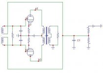
At least with your figure of bias shift. However I noted
that (if you have a set up similar to that in the following pic)
If the value of the capacitor C1 is small a shift occurs.
So, try a large valued cap. 1000u or even more.
ciao
Attachments
For instance the 50 ohm balance pot on the 6SN7 cathode has little to no effect on distortion.
Hi
I would avoid that pot. As for me, you need only one dynamic balance control. After some trial I found that you can sobstitute
the two 470k res at the 12b4a grids with a 100k linear pot.
It seems quite effective in changing 2nd harm content
at the output. So, if the 12b4a are statically well coupled
( to avoid static flux in the trafo), you can use only two
regulations : a static one for the 845 (grid bias) and a dynamic one at the 12b4a grid to minimize even order harm. (but
remember that sometimes sound appear subjectively better
with lot of 2nd harm, a question of taste)
bye
Federico
bias again
Hi Federico,
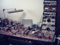
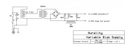
This is the circuit I am using for the fixed bias. I think it is a connection or layout problem I am having. If you remember the picture of the breadboard it is a scary thing to figure out.
What I know is that as connected now, with signal level dependance the grids of the 845s becomes more negative and this requires only that filaments be lit, i.e. it does not require negative bias supply or B+ voltage. Still thinking about what the hell I have wrong.
For the heck of it, while I am thinking, I wired the stage up as cathode bias. Works fine and in fact sounds fine, I am listening now.
Am rethinking aspects of the frontend as well. I think I have a busy few days ahead.
Michael
Hi Federico,
This is the circuit I am using for the fixed bias. I think it is a connection or layout problem I am having. If you remember the picture of the breadboard it is a scary thing to figure out.
What I know is that as connected now, with signal level dependance the grids of the 845s becomes more negative and this requires only that filaments be lit, i.e. it does not require negative bias supply or B+ voltage. Still thinking about what the hell I have wrong.
For the heck of it, while I am thinking, I wired the stage up as cathode bias. Works fine and in fact sounds fine, I am listening now.
Am rethinking aspects of the frontend as well. I think I have a busy few days ahead.
Michael
Attachments
A2 and bias
Hi Federico, All,
I have tried many different grounding schemes for the bias setup and now even rewired it as a bipolar supply and tried the bias transformer ct at various ground points. The magnitude may change slightly, but the overall story is that the grids still go strongly negative in proportion to the signal level. I also tried a 3500 uF cap across the bias, per your suggestion Federico. I think maybe you didn't run the model long enough, it still goes negative, just takes longer. Anyone have any thoughts?
I haven't really measured the output distortion in a systematic way, but piecemeal results suggest the distortion is strongly dominated by the 845s and many changes can be made to the frontend operating points with only small effects on the output distortion. By the way, I changed the 6SN7 cathode scheme to diode bias using a 6H6. Also, I tried the 100k pot in place of the 470k grid resistors on the 12B4, but I saw little change in the output. Maybe later I will try some measurements on the plates of the 12B4 and see what it looks like there. I had to take a break yesterday to do my taxes, nothing like the last minute for me.
Michael
I think maybe you didn't run the model long enough, it still goes negative, just takes longer.
yes, you are right Michael
it seems unavoidable since, in this implementation,
grid current plays like a rectifier.
Negative supply is subjected to current pulse which
always are in the same direction. So slowly the cap
is charged and B- become more and more negative.
I actually see only two causes that control the magnitude
of the phenomenon:
1) amount of grid current (it might be
greater than the sheet told us)
2) DC resistance of the B- supply.
However, I think that with real music, if the characteristic time
of the shift is of the order of a few seconds, the amp will
sound good. I do not think that we have more than 2-3
seconds of continuative positive grid in a real listen.
So, big cap.
everyway I'll continue to search a method to avoid the bias
shift, but I don't know if such a method does exist.
Any idea?
Federico
grid current
Hi Federico, All,
The amount of grid current is small as the sheet showed. Mostly it seems to be in the microamp to low milliamp range.
Not that I can use it, but I would like to be able to say the amp could run in A2 continously. I wonder how this problem was resolved in the past? I have tried many bias supply setups and none makes a substantial difference, although there are differences. The DCR of the circuit I posted should be very low I would think. Anyway, have a look at this site, http://www.icl.co.jp/audio/english/2a3/2a3amp.htm
I just did another rewire of the breadboard to consolidate supply grounds and clean up the setup and now I have another problem, variants of which I have seen before, where the 12B4 current goes down dependant on input signal level. Oh well, someday it will be straightforward.
Michael
woohoo
Woohoo and Doh'
Everything is working properly finally. I've gotten the hum voltage down to ~10mV pk-pk at the speaker output. All valves conduct properly with no signal dependant changes. And I figured out why I had that gas diode in my bias supply schematic I drew so long ago. With the addition of an 0A3 and a 1.5k resistor I can now vary the bias between -78 and -95 volts while remaining well within the limits of my bias supply and the 0A3. The bias drops a couple of volts max when the 845s are pushed into A2. In addition the humpot I am using at the moment puts the filaments 8V positive, so I am biasing at 86V with 645V on the plates and 170mA current the pair. Now with no particular optimization done, max output is at 42.75W when driven from my computer signal generator.
Wow does this thing do kick drums.
Michael
Hi
Compliments Michael
I am very happy, really.
BTW, where was the problem with the bias shift?
regarding balance, can you tell me the individual static currents.
bye
Federico
Compliments Michael
I am very happy, really.
BTW, where was the problem with the bias shift?
and 170mA current the pair
regarding balance, can you tell me the individual static currents.
bye
Federico
bias shift
Hi Federico,
It seems the bias shift came from the caps in the bias supply charging from the signal. After I put in the VR tube I implemented the static bias scheme and the problem returned to a degree. I rewired the supply this morning and also implemented the dynamic feedback bias adjustment. The bias shifts about 5 volts at steady full output. The dynamic circuit does work, by the way. It can change 2nd harmonic significantly and has a small effect on third. In your schematic you show a 2uF coupling cap between the plate and the 1660 CT. Is it necessary for it to be that large? I am just using a 0.22uF at the moment because that is all I could dig out that was rated at 1000VDC. Also am using a 180k resistor instead of the 200k you used in the simulation.
I still do not have a good method to measure the static current in the individual 845s. Any suggestions? I am using a single AC transformer for both filaments at the moment. Maybe this afternoon I will have a few minutes to temporarily add a second transformer so I can have separate filament supplies.
Federico, what does your model show for intermodulation of the 1k signal with the 60Hz filaments? I am seeing a significant amount.
Michael
hi
0.22u and 180k are good.
what about putting an 1 or 10 Ohm resistor (very precise) at
the anode of both the 845s?
The model does not include filament.
If, once the hum will be minimized by an appropriate pot,
it will be still too high then, maybe, a rectifier is needed.
IMPORTANT:
substitute the 1nF cap between the 845 grids with
two 1nF cap between grid and ground. This will be much more
effective in preventing possible instabilities.
Federico
I am just using a 0.22uF at the moment because that is all I could dig out that was rated at 1000VDC. Also am using a 180k resistor
0.22u and 180k are good.
I still do not have a good method to measure the static current in the individual 845s. Any suggestions?
what about putting an 1 or 10 Ohm resistor (very precise) at
the anode of both the 845s?
what does your model show for intermodulation of the 1k signal with the 60Hz filaments? I am seeing a significant amount.
The model does not include filament.
If, once the hum will be minimized by an appropriate pot,
it will be still too high then, maybe, a rectifier is needed.
IMPORTANT:
substitute the 1nF cap between the 845 grids with
two 1nF cap between grid and ground. This will be much more
effective in preventing possible instabilities.
Federico
- Status
- Not open for further replies.
- Home
- Amplifiers
- Tubes / Valves
- 845 PP and Lundahl 1620