test now
Hi Federico,
I will test now the output of the 1660 with varying load from 5k to 100k with the input level set to that which gives 100Vrms output end to CT with 100k load. I will try to post some results soon.
I am afraid I am still not very good at MicroCap. What does the input impedance of the 845 grid reach as a minimum when in the positive grid region? How much power is the 12B4 expected to deliver? When I measured in the past it seemed like I saw ~1-1.5 mADC and maybe 2.5-3mA AC in the grid circuit. I was never sure if these measurements were correctly done though.
Will also try to post some preliminary and very unoptimized distortion numbers for the 845 output. Hopefully this morning.
Michael
What does the input impedance of the 845 grid reach as a minimum when in the positive grid region?
When no grid current input res is infinite. When current appears
there will be by definition a resistence given by V/I.
Really things are quite different. However at 50Volts positive
the grids gives 4 mA.
In that condition The model shows a small signal resistance of
about 6k.
At 25V positive it reduce to 0.7-0.8 mA with a small sig. res of
about 18k. An excellent permormance.
This is a model , naturally.
Federico
thanks and data
Hi Federico,
Thanks for the answer on input admittance. This is kind of good news/bad news.
The data from the load impedance test. Feel free to comment. The circuit was as you have drawn above except 110 uF capacitance rather than 100 uF, the 80k resistor on the primary is 100k and the voltages I am using on the 12B4 are a little lower than in the past. 214V plate and 27.3V bias. Data collected with signal on grid of 12B4 at 20V by multimeter, maybe the edge of grid current for it too?
Michael
Attachments
definitely my model is different.
At first I have to give 240V to b+ in order to have
27.3V bias. (yes, 20Vrms as input is sligth grid positive)
Then put the cap from CT to ground to have results more
similar ( at least qualitatively, wiht a minimum) to
yours.
you see less voltage loss that is my model
has smaller internal res.
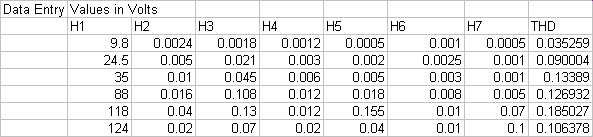
I write only odd harm since even are obviously very small
because balance is perfect.
here is my table
Federico
However maybe you need a better driver.
At first I have to give 240V to b+ in order to have
27.3V bias. (yes, 20Vrms as input is sligth grid positive)
Then put the cap from CT to ground to have results more
similar ( at least qualitatively, wiht a minimum) to
yours.
you see less voltage loss that is my model
has smaller internal res.
I write only odd harm since even are obviously very small
because balance is perfect.
here is my table
Federico
However maybe you need a better driver.
Attachments
Michael,
I’m having a little problem following your test point’s can you please clarify where each point is in the circuit. I assume these are nodes in your simulation model.
As for the load on the driver, I leave the plate side open as the impedance seen by the driver tube will be the impedance on the output side times the turn’s ratio squared. So for a 2.25:2 the impedance is the 6.25 % greater. 100k on the output side would be 106K on the input side. So if you then put a parallel load there you are loading the tube extra hard.
That’s the way I see it. All that you should have to do is adjust the output side for your best performance.
I’m still interested in your schematic.
Thanks,
Chuck
845 data etc
Hi Federico, Chuck
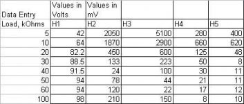
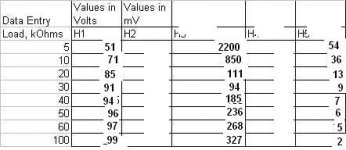
Federico, our results are not terribly different I think. The operating point I was using was chosen yesterday for least distortion at a higher B+ on the 845 and it is probably not the optimum on it's own. I think there is some synergy in the higher order harmonics with some cancellation in the overall output. Anyway, the data below is with the old operating point, with the 100k on the primary of 1660, 220k on secondary and 110uF to cathode of 12B4. Dynamic balance is used but not totally optimized for 2nd order. Vp on the 845 was 645 and current 82mA bias is assymetrical to balance current, but around -84V.
Chuck, the data above was just collected from the 1660 output of one side to the CT with a varying load across the whole of the secondary. The data below is from the output of the 1620 into an 8 ohm load.
Will try to get the schematic for the bias done, but today and maybe tomorrow are busy days for me. I think I am done playing for the day.
Michael
Hi Federico, Chuck
Federico, our results are not terribly different I think. The operating point I was using was chosen yesterday for least distortion at a higher B+ on the 845 and it is probably not the optimum on it's own. I think there is some synergy in the higher order harmonics with some cancellation in the overall output. Anyway, the data below is with the old operating point, with the 100k on the primary of 1660, 220k on secondary and 110uF to cathode of 12B4. Dynamic balance is used but not totally optimized for 2nd order. Vp on the 845 was 645 and current 82mA bias is assymetrical to balance current, but around -84V.
Chuck, the data above was just collected from the 1660 output of one side to the CT with a varying load across the whole of the secondary. The data below is from the output of the 1620 into an 8 ohm load.
Will try to get the schematic for the bias done, but today and maybe tomorrow are busy days for me. I think I am done playing for the day.
Michael
Attachments
above data
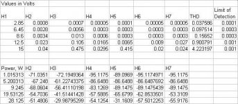
The data above was not collected under optimized conditions, just conditions where I know the values in case asked. Because I have not felt that I have moved beyond the "make sure everything is hooked up right" stage, the data I collected in the past was just sort of an aside to adjustments in circuit arrangement and usually devoid of operating conditions. Probably about the best I have seen on the high power end is something around 1.5% distortion at 25W.
Michael
12B4
Hi Federico,
What I am confused about - when using a 10k output transformer I seem to remember being able to swing around 300V peak to peak on the primary. Why would performance be drastically worse with the 18k load reflected back as something over 20k with the 1660? Something doesn't seem right.
Michael
when using a 10k output transformer I seem to remember being able to swing around 300V peak to peak on the primary.
Excuse me Michael, due to my badly knowledge of your language
I am not sure to fully understand your sentence.
What 10k OPT? loaded with what resistance?
300 p-p is practically 105 Vrms, right?
please, be so patient to explain me.
thanks.
Another thing:
Think to this story: A hypothetical driver is able to deliver 100Vrms when loaded with a 100k res with a distortion of 0.0001%. But it has a high internal res. So, when loaded with 10k it delivers only ,eg, 70Vrms, but always with 0.0001%. It is a very good (linear) driver but with a high internal res. What happen when it is called to drive a positive grid?
The resistance of the load is now variable. Very high when grid is negative but low, say 10k or less, when it become positive, the wave on the grid will have an abrupt change of shape: a perfect
100Vrms sine wave with grid neg. with the peak made of a perfect 70Vrms sine wave.
This is a highly distorted signal. So, irrespective of the fact that the driver has a very low distortion with every load, when the load is variable (with amplitude) it , due to high internal res, distorts very much becoming a bad driver.
This effect add up to the fact that your driver distorts a lot at low load.
federico
driver
Hi Federico,
I am referring to the previous thread discussing the 12B4 optimization. An output transformer was used with a 16 ohm load that reflected as 10k.
I understand this (though I had kind of forgotten about it). Very nice explanation. What I was thinking of was the test from yesterday. Why did performance become so much worse when only approaching in a steady state manner the load resistance used previously for testing with good results? I think the internal resistance of the 12B4 should be around 1k here, which is pretty low for a tube. What options can you suggest? Try other tubes, as 316a suggested, or change the configuration or CCS load, or pentode as cathode follower direct coupled to 845 or raise B+ and stay in A1? Throw out some ideas Federico (or anyone).
Thanks,
Michael
Hi Federico,
What 10k OPT? loaded with what resistance?
300 p-p is practically 105 Vrms, right?
I am referring to the previous thread discussing the 12B4 optimization. An output transformer was used with a 16 ohm load that reflected as 10k.
The resistance of the load is now variable. Very high when grid is negative but low, say 10k or less, when it become positive, the wave on the grid will have an abrupt change of shape: a perfect
100Vrms sine wave with grid neg. with the peak made of a perfect 70Vrms sine wave.
I understand this (though I had kind of forgotten about it). Very nice explanation. What I was thinking of was the test from yesterday. Why did performance become so much worse when only approaching in a steady state manner the load resistance used previously for testing with good results? I think the internal resistance of the 12B4 should be around 1k here, which is pretty low for a tube. What options can you suggest? Try other tubes, as 316a suggested, or change the configuration or CCS load, or pentode as cathode follower direct coupled to 845 or raise B+ and stay in A1? Throw out some ideas Federico (or anyone).
Thanks,
Michael
Re: driver
Hello ,
It may be an idea to change the 845 output transformer from 11k to 5.5k and increase the HT to 750-800V keeping the driver as-is . You should get a distinct improvement in power output in class A1 . Only problem with this would be a slight increase in 3rd harmonic and lower damping factor . I ran a few sims with 11k a-a loads last night and you really need at least 900V for this load
cheers
Nic
audiobot said:Hi Federico,
I am referring to the previous thread discussing the 12B4 optimization. An output transformer was used with a 16 ohm load that reflected as 10k.
I understand this (though I had kind of forgotten about it). Very nice explanation. What I was thinking of was the test from yesterday. Why did performance become so much worse when only approaching in a steady state manner the load resistance used previously for testing with good results? I think the internal resistance of the 12B4 should be around 1k here, which is pretty low for a tube. What options can you suggest? Try other tubes, as 316a suggested, or change the configuration or CCS load, or pentode as cathode follower direct coupled to 845 or raise B+ and stay in A1? Throw out some ideas Federico (or anyone).
Thanks,
Michael
Hello ,
It may be an idea to change the 845 output transformer from 11k to 5.5k and increase the HT to 750-800V keeping the driver as-is . You should get a distinct improvement in power output in class A1 . Only problem with this would be a slight increase in 3rd harmonic and lower damping factor . I ran a few sims with 11k a-a loads last night and you really need at least 900V for this load
cheers
Nic
Michael
Now I am confused too. With similar load I expect similar
results on the primary. If not I see only two possible causes
a) different working point of 12b4a
b) saturation of 1660
What do you think?
Nic
I think 845 can give us much more. It is a very good tube,
maybe the best, regarding grid current and A2 operations. The output stage appears good as is. The driver needs further work, IMHO.
Bye
Federico
What I am confused about - when using a 10k output transformer I seem to remember being able to swing around 300V peak to peak on the primary. Why would performance be drastically worse with the 18k load reflected back as something over 20k with the 1660? Something doesn't seem right.
Now I am confused too. With similar load I expect similar
results on the primary. If not I see only two possible causes
a) different working point of 12b4a
b) saturation of 1660
What do you think?
Nic
It may be an idea to change the 845 output transformer from 11k to 5.5k and increase the HT to 750-800V keeping the driver as-is . You should get a distinct improvement in power output in class A1
I think 845 can give us much more. It is a very good tube,
maybe the best, regarding grid current and A2 operations. The output stage appears good as is. The driver needs further work, IMHO.
Bye
Federico
try again
Hi Nic,
Higher B+ is always an option. I happened onto three 2uF 2500VDC Sprague paper and oils yesterday that could be used for small uF cap input. When I modelled lower impedance transformers in SEAmpCad (easy) and looked at 3rd harmonic I saw what I would call a large increase going from 6.5k transformer to 3.5k. I think that should be close to the proper equivalent of going from 11.5k to 6.5k for PP?
Federico,
I am confused much by the difference in results from the 10k OPT to the 1660 with different loadings. According to the Lundahl datasheet, the 1660 should be good for 2x230Vrms at 30Hz. So it shouldn't be saturating, unless something is wrong with one of the tubes and I have very assymetrical current in the primary. But then I would think I would never get low distortion and I did at high loadings. I will try the experiment again at the original operating point, and maybe recheck again all of my connections. Also maybe try a few other small experiments that might offer some sort of information that may be useful taken in the whole.
Michael
michael
I read the .pdf, but I think that such data is quite meaningless since rms voltage has little to do with core saturation (if load is not specified) which depends on current.
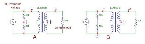
However, as for me, you are able to verify the saturation performance of the 1660 by means of your variable 60 Hz supply.
If you can have it balanced (floating) you can use configuration (A) , otherwise follow config. (B). By varying the load and looking at the wave in (p) [or (p1)] you would be able to verify the quality of the trafo.
Reading at (o) has to be 20 Vrms while, naturally in (o1) (B config.) you will read 40 Vrms.
Federico
According to the Lundahl datasheet, the 1660 should be good for 2x230Vrms at 30Hz.
I read the .pdf, but I think that such data is quite meaningless since rms voltage has little to do with core saturation (if load is not specified) which depends on current.
However, as for me, you are able to verify the saturation performance of the 1660 by means of your variable 60 Hz supply.
If you can have it balanced (floating) you can use configuration (A) , otherwise follow config. (B). By varying the load and looking at the wave in (p) [or (p1)] you would be able to verify the quality of the trafo.
Reading at (o) has to be 20 Vrms while, naturally in (o1) (B config.) you will read 40 Vrms.
Federico
Attachments
1660 test
Hi Federico,
I can try the test you showed. I have a floating variable supply that I am using for the filaments. It can be varied from 0-25V. How did you pick the 20Vrms, or was that just used to indicate the double voltage necessary for a single ended supply?
I thought that for AC current/voltage in the transformer it was the voltage that determined saturation and current that determined the power level. I must be confused.
Michael
Hi Michael, all,
I did some experimenting with different loads for the 845’s with bench and listening tests using my Quad ESL63’s.
I started with the 6k load and found that it gave me the most power out on the bench but didn’t control the base as well as the 3.3k setting. I then tried the 11.5K and the base became boomy.
I have a speaker impedance matching transformer called a Zero See http://www.zeroimpedance.com/ that allows easy changing of the load and have found that a lower plate load helps control the base. One of these days I hope to have my listening room setup again and I can do more listening tests with some of my dynamic speakers.
As for the power output, on the bench I could get about 63 watts with the 6k and about 45 with the 3.3K either way they drove my quads well. (P+ of 1050V)
Chuck
1620 et al
Hi Chuck, all,
Chuck, do you think the bass boominess with the 11k setting could be because you were approaching or reaching saturation of the 1620? It's only rated at 63W in that configuration. I thought the higher impedance ratio would offer better speaker control? I know from the simple models I have run it models with greatly reduced 3rd harmonic distortion, ie an order of magnitude. Just had another look at your schematic and I must say I like it.
Federico,
Much as I like the idea of A2 and the lower B+ that goes with it, I must say I like this driver setup too. I know my gain margin is not great and there are probably other things that could be improved, but I just did a measurement that makes me remember how good I think it sounded and measured on it's own.
With no load on the primary of the 1660 and a 50k load on the secondary I got these numbers.
output from 1676 input (grid of 6SN7)- 1.55Vrms
on grid on 12B4- 21.3Vrms
12B4 cathode at 30.7VDC without signal and 31.2VDC with signal
~295V pk to pk on plate of 12B4 by scope
100Vrms on secondary 1/2 of 1660
H2=320 mV
H3=70mV
H4=15mV
H5=44mV
H6=<1mV
H7=10mV
H>7=<1mV=below limit of detection
Do you think I can come close to those numbers, and given that I know that on it's own this circuit sounds very, very good, with a setup that can deliver the necessaries for A2 function? I'm torn.
Michael
sinewave before
Hi All,
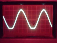
I decided to run a complete distortion vs volts output on the 12B4 with a 50k load on the secondary of the LL1660S. When I got to 125Vrms, the highest I tried and almost certainly overdriving the grid of the poor 12B4, I got this picture on the scope from the primary of the 1660
M.
Hi All,
I decided to run a complete distortion vs volts output on the 12B4 with a 50k load on the secondary of the LL1660S. When I got to 125Vrms, the highest I tried and almost certainly overdriving the grid of the poor 12B4, I got this picture on the scope from the primary of the 1660
M.
Attachments
sinewave after
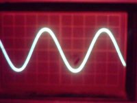
This is the picture, all conditions unchanged except the location of the 10x scope probe, on the secondary 1/2 to CT. Class AB or just a general cleaning up? I guess I've not looked often at the primary side of a transformer before.
M.
This is the picture, all conditions unchanged except the location of the 10x scope probe, on the secondary 1/2 to CT. Class AB or just a general cleaning up? I guess I've not looked often at the primary side of a transformer before.
M.
Attachments
- Status
- Not open for further replies.
- Home
- Amplifiers
- Tubes / Valves
- 845 PP and Lundahl 1620