I am partial to the 211 and 845 output tubes. I am curious as to all the different drive circuits that have been used in these designs.
I have been experimenting with a few different driver circuits using common tubes that do not draw major current such as the 6BL7/ 6BX7 tubes.
Circuit 1 - 6SL7 (Both sections paralleled - grounded cathode) direct coupled to a 6SN7 (Both sections paralleled - cathode follower) driving a 211;
1050 plate voltage
Custom 16k OPT
14 watts RMS @ 5% THD
Circuit 2 - 6SN7 (SRPP) direct coupled to a 6SN7 (Both sections paralleled - grounded cathode) driving an 845;
810 plate voltage
3.2k OPT
19.5 watts RMS @ 5% THD
I have pretty good results using 417A/5842 into a 6AH4 triode for driving an 845. A single 12HL7 will just about get you there in terms of gain. I'd like to try one of those with something like a 12B4 cathode follower.
Here's a preliminary design I'm working on that makes use of the 845.
This one uses the 6DR7, a dissimilar dual triode for use as a vertical deflection oscillator/amp. The small signal half is a high-u triode that gives a decent gain margin for this. The large signal section can stand up to the high voltages that the large input swing (310Vp-p) that the 845 requires. Active plate loading here maximizes the output swing and linearity.
These DHTs have a nasty habit of pulling grid current even before Vgk actually swings positive. To handle that, and also source the current needed to charge up Cgk + Cmiller + Cstray, as well as handle the occasional transient clip, use a source follower as a grid driver.
Also, incorporate variable gNFB.
Attachments
Stay away from a driver that is RC coupled to the 845 / 211. An IT or cathode follower driver will provide sufficient drive for the output tube. Sounds much better.
If you aren't adverse to solid state devices, check out tubelab's web pages for good stout drivers for big triodes. I think he calls it "power drive".
Daniel
3.2K is low for an 845. It likes to see an OT of around 7K ohms. 16K ohms is good for the 211. Higher OPT impedence reduces output power only slightly and it reduces distortion quite a bit. It also increases damping factor. Both of these things are good.
If you are doing this single ended you will have problems with filament hum on the big triodes. Getting a low noise filament supply will take some doing.
Last edited:
Thanks for all the reply's.
I am not necessarily against mixing different technologies, but would like to stay all tube based for this experiment. No problem with hum from my 211 / 845 DHT amps, just have to have a good (beefy) filament x-former, good caps and a decent DC circuit.
I am working my way up to using other tubes for the final driver, but wanted to start off with basic tubes and see (and hear) the results . Circuit 2 is driving the 845 as is referenced in the RCA 845 data sheet, except the x-former is supposed to be 3.4k. Extrapolating the data for the plate voltage and bias points I used, 19.5 watts RMS is right on target using the low impedance OPT.
Yes, more primary impedance is better, but I wanted to verify the Chinese 845 operating points by using this configuration. Seems like the Chinese 845 are close to the originals as we all have suspected. Not a bad tube for the money.
At 1 watt, the 845 output THD (with driver circuit 2) is only 0.2%. Not bad for a couple of common octal tubes.
Last edited:
One of the best driver you can use is the Alan Kimmel choke coupled MuStage. Look up the last two issues of VTV magazine on it. The choke coupled MuStage does it all (1)Wide bandwidth (2)Low distortion & very linear (3)Very good PSRR(4)Low output impedance with High drive currant
(5) No driver system is more consistent and versatile than the choke couple MuStage.
. You can use a lot of input tubes that would not work as well,like a EF86 Mesh plate or a Russian 310A.For a wild combo try the pentode of a 6bm8 input 7591 driver,you could get well over 800vPP with that combination. If you what to use your 6sl7 try a EL86 for a driver.
One last thought about choke couple MuStage,it work really well with a interstage transformer because
it has the low output impedance with good currant. Give it a try you will not reget it.
845 25 Watts Per/Channel with input ^SN7 And Driver 6SN7 Tube
Dear Friend,
I am planning a 25 to 28 Watts Per Channel Single Ended Class A AMP using a 6SN7 Input Tube and a 6SN7 Driver Tube to Drive The 845 Power Tube, have you got The Power Supply Schematic Circuit and The Driver Circuits , I plann on using a DOUBLE C Core 70 Watts Transformer on Each Mono Block, all your help will be Appreciated, I am not a Qualified Technician, but do have a Friend Who has got over 45 years experience in Tube Power amps. And if I got the right Schematic Circuits he will attempt to build it for me.
Your Help will be appreciated.
Kind Rgds
Francis Jansz
Melbourne, AUSTRALIA
I am partial to the 211 and 845 output tubes. I am curious as to all the different drive circuits that have been used in these designs. <snip>
Dear Friend,
I am planning a 25 to 28 Watts Per Channel Single Ended Class A AMP using a 6SN7 Input Tube and a 6SN7 Driver Tube to Drive The 845 Power Tube, have you got The Power Supply Schematic Circuit and The Driver Circuits , I plann on using a DOUBLE C Core 70 Watts Transformer on Each Mono Block, all your help will be Appreciated, I am not a Qualified Technician, but do have a Friend Who has got over 45 years experience in Tube Power amps. And if I got the right Schematic Circuits he will attempt to build it for me.
Your Help will be appreciated.
Kind Rgds
Francis Jansz
Melbourne, AUSTRALIA
Last edited by a moderator:
Francis,
I am traveling now, but when I get back home, I will post a full schematic.
All my circuits are on my personal laptop (I only have my work laptop now).
Unfortunately, I will not be home until the end of April.
I am traveling now, but when I get back home, I will post a full schematic.
All my circuits are on my personal laptop (I only have my work laptop now).
Unfortunately, I will not be home until the end of April.
845 Single/Ended Pwr/Mono/Block Amps With 6 SN 7 Input and 6 SN 7 Driver Tubes
Hi I am interested in Trying to Build The S/E Power Mono Block Amps with The Following Tubes 6 SN 7 Input Tube + The 6 SN 7 Driver Tube + The 845 Output Tube and Intend Using a Double C Core 70 Watts Output Transformer and I hope to get around 24 to 25 Watts Per Channel on Each Mono Block , I am seeking for The Power Supply Schematic Circuit and The Filament Circuit Voltages to Achieve this, I believe that The Transformer will be Giving out around 1100 Volts, And it will be Hand Wound by a SCOTT ELECTRONICS in Dandenong ,Victoria.
I would appreciate a Full Working Schematic Circuit so I can get a Technician to Construct This AMP,Any help is appreciated.
Kind Regards
Francis Jansz
fsj@iprimus.com.au
Could be a variation of this:Dear Friend,
I am planning a 25 to 28 Watts Per Channel Single Ended Class A AMP using a 6SN7 Input Tube and a 6SN7 Driver Tube to Drive The 845 Power Tube

Like:

btw, could anybody suggest on how to mod the above schematics to replace the cap with interstage transformer?
btw, could anybody suggest on how to mod the above schematics to replace the cap with interstage transformer?
I´d go PP interstage, symmetric input (balanced) 6sl7 RC -> 6v6/6c19pi triodes wired to primary. Secondary wired to 845 grid
211 and 845 are not small amps .if we have big tube amp in our room ...sound should be different. did you hear sound of good 211 or 845 amp?
Thank you for the info on the 6sn7 and 845 circuit. I will send it to my technicianCould be a variation of this:
<snip>
btw, could anybody suggest on how to mod the above schematics to replace the cap with interstage transformer?
The 6SL7 tube is not suitable for interstage coupling. You need to use a tube that has a much lower plate resistance. In addition, the circuit topology is not correct to use an interstage transformer.Could be a variation of this:
<snip>
btw, could anybody suggest on how to mod the above schematics to replace the cap with interstage transformer?
The ECC82 is amazingly linear at high voltages, and Tubelab's PowerDrive is almost transparent, so this should work for big triodes
Neither capacitor nor transformer between driver and output tube grid. 😉
Unlike the 6SL7, the ECC82 Vkh is within specs.
Neither capacitor nor transformer between driver and output tube grid. 😉
Unlike the 6SL7, the ECC82 Vkh is within specs.
Attachments
Last edited:
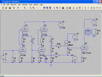
This design was intended for the 211, it is just a simulation, I abandoned the project due to the 16K output transformer, it is very difficult to design and build.
The design is also suitable for the 845, with higher input voltage, and adequate bias.
I have four Chinese 211, branded as GE 🙄, and have a lot of ECC82/12AU7 some "Germans" RSD, RCA, Tungsram, Philips Miniwatt, EI... none of them has disappointed me.
ECC82 in SRPP is foolproof, neutral and transparent, even better at high voltages, note that three 325V series connected power supplies would give 650V and 975V for the 211.
Last edited:
Ref: 6 SN 7 Input and ^ SN7 Driver for 845 Power Amp,
I am not a quallified technician, but do have a Friend with 50 years experience that may be able to build the AMP for me. any advise or help will be greatly appreciated.
Kind Rgds
Francis Jansz
From: Melbourne, AUSTRALIA
Dear Friend I hope that you are back on from your vacation, and will wait patientely for the Power Supply Schematic using a Choke and a Small Transformer to The FILAMENT , to drive the 845 power amp. and what's the very best Output Watts that I can get using a 70 watts Double C Core Output Transformer at 1150 VOLTS. will i be able to get around 25 to 28 watts on each mono block.Francis,
I am traveling now, but when I get back home, I will post a full schematic.
All my circuits are on my personal laptop (I only have my work laptop now).
Unfortunately, I will not be home until the end of April.
I am not a quallified technician, but do have a Friend with 50 years experience that may be able to build the AMP for me. any advise or help will be greatly appreciated.
Kind Rgds
Francis Jansz
From: Melbourne, AUSTRALIA
Hi,
check this 211 driving a 845 setup DC connected.
the setup is working. we tried out this setup during ETF some years ago in Berlin with big EIMAC tubes 250TL I think. “death machine”
please see Röhrenverstärker | silvercore Blog | Page 2
best regards
Karsten
check this 211 driving a 845 setup DC connected.
the setup is working. we tried out this setup during ETF some years ago in Berlin with big EIMAC tubes 250TL I think. “death machine”
please see Röhrenverstärker | silvercore Blog | Page 2
best regards
Karsten
Attachments
- Status
- Not open for further replies.
- Home
- Amplifiers
- Tubes / Valves
- 845/211 driver circuits