I just came back and looked at this thread - it seems that the schematic that I had to pull from post 38 has now reappeared in post 39, replacing the corrected version (probably something to do with them both having the same file name). That schematic won't work - the pentode CCS will have nowhere near enough voltage across it.
Just so that this is not a completely useless post, I've re-attached the corrected version, albeit now without the gas regulator (couldn't be bothered redrawing it).
Just so that this is not a completely useless post, I've re-attached the corrected version, albeit now without the gas regulator (couldn't be bothered redrawing it).
Attachments
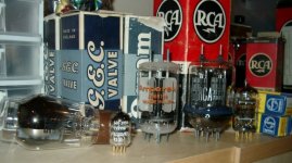
I was very happy to receive a parcel this morning, so here is a picture of some valves sitting on my very crowded chest of drawers. All of them are pentodes or beam tetrodes and were not intended for audio (not that we care 😉)- the leftmost one is a regulator pass valve, and the rest are RF types.
From the left to right we have 12E1 (35W), E180F/6688/CV3998 (3W), YL1071/8116 (60W), 829B (30W), and E55L/8233 (10W).
This is not a completely gratuitous post, the point I'm trying to make is that the 8116/YL1071 is physically very small for its rated maximum anode dissipation.The suggestion somewhere here of mounting the valve base into a computer fan guard for convection and directing some forced air at it is probably a very sound one for the YL1071/8116. As you can see, the thing is physically around half the size of 12E1 and slightly smaller than 829B - while having around twice the dissipation rating! This is one hot little valve
I've finally done something useful and worked out the component values for the 8116 amp for Shane (who kindly sent me the valves - thank you!), so I'll post that next.
Attachments
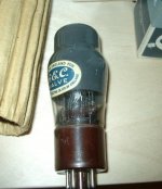
Yl 1071
Yes I think that the likes of YL 1071 would get warm. One feature I like is the fact that the heater requires on 11W - few 60W valves can match that!
However, note the finning on the anodes which would help - compare and contrast with an old-fashioned type like 12E1.
As I wrote before I have been running QQVO7-50s at 44W for two years with only minimum cooling - mind you, one of them packed up the other day!
However, I think that for a valuable type like YL 1071, it would be well worthwhile to turm up some finned anode connectors to get a bit more heat away from the anodes and reduce the strain on the upper glass-to-metal seal
7N7
Hi,
Sorry about the QQV07-50 🙁 Never nice to hear about valves dying!
Yep, the 12E1's anode is rather old-fashioned, but its larger bulb means that the glass (and importantly, the glass-metal seals) will be somewhat cooler than smaller types like the 8116.
I think I might have made a mess of things again with the schematic, so I'll wait till tomorrow when everything will hopefully be a little clearer. 😀
OT: (but not many people seem to be posting here anyway...) I have a few KT33s and they all have this greyish coating on the inside of the valves. Do you this coating something like mentioned in Valve Amplifiers about carbonised envelopes reducing electron deflection due to the glass envelope gaining a charge - I'd suspect it might hinder radiation a bit though....
Attachments
Firstly, I've managed to come up with something using only valves from Shane's junk box. No need to buy things if you already have them 🙂
I've drawn something which gets b (the feedback fraction) up to around 0.45 or so, I'd like it to be higher, but that isn't really possible without pentodes as the upper valves in the m-follower drivers - and I'm not sure if it's worth the effort. Well, there's one possible upgrade path right there 😀
As it stands, there is about 17dB of negative feedback from the anodes of the 8116 to the grids of the 5670s.
Also, the output is biased into class A (which I think is required for accurate phase splitting - some real engineering knowledge might help here 😉), so the valve is dissipating 56W or so at the anodes (28W each).... A little forced air will go a long way. Heavily biased class AB would probably will be more sensible, but I think it might necessitate a separate phase splitter because class B loading will make the loads on each half of the differential pair different and affect phase splitting accuracy. Likely a simple concertina at the inputs would do the trick (more subtly this also allows R21 and R22 to be a little larger, increasing the effective ra of the 5654s and thus increasing the feedback ratio)
The current design makes me somewhat nervous for the life of the 8116s for several reasons, heat considerations being only one of them. If for some reason the 5670/5654 stop conducting I imagine the grids of the 8116s will head towards B+, likely destroying the poor valves Perhaps some thought by more experienced minds here is needed. So far, I've thought of a fuse in parallel with a large-ish value resistor in the cathode lead, so that the fuse will blow and the resistor will bias the output valve into cutoff should the valve draw excess current. I'm sure there's a more elegant solution.
The power supply will also require that the output valves are not drawn into excess conduction as a result of the grids being at some positive voltage until everything is conducting and conditions are stabilised. I would imagine the simplest solution is a valve rectifier (and it's slower warmup) for the driver's B+ (but not B-). One of the smaller less popular B9A types would probably be sufficient because the current draw is not very large.
A Maida regulator for the screens would be nice. Plus, it isn't very complicated.
I haven't calaculated the value of C5, I hope it's sufficient 😉
R17 and R18 consist of series connected resistors because they collectively have 421V across them and I'm not sure what the voltage rating of modern resistors is - hopefully it's more than the 53V they'll see 🙂
Another problem: power output is a measly 15W - not exactly low power, but this represents a paltry 27% of the total 8116 anode dissipation. It is quite possible a better operating point could be chosen.
The resistors with value "GS" are gridstoppers - they may not really be necessary (there to prevent HF oscillation). Also, the main B+ is marked as 290V but that allows for 10V drop across the OPT primary's Rdc, so the voltage at the anodes is really 280V.
Anyway, here ya go:
I've drawn something which gets b (the feedback fraction) up to around 0.45 or so, I'd like it to be higher, but that isn't really possible without pentodes as the upper valves in the m-follower drivers - and I'm not sure if it's worth the effort. Well, there's one possible upgrade path right there 😀
As it stands, there is about 17dB of negative feedback from the anodes of the 8116 to the grids of the 5670s.
Also, the output is biased into class A (which I think is required for accurate phase splitting - some real engineering knowledge might help here 😉), so the valve is dissipating 56W or so at the anodes (28W each).... A little forced air will go a long way. Heavily biased class AB would probably will be more sensible, but I think it might necessitate a separate phase splitter because class B loading will make the loads on each half of the differential pair different and affect phase splitting accuracy. Likely a simple concertina at the inputs would do the trick (more subtly this also allows R21 and R22 to be a little larger, increasing the effective ra of the 5654s and thus increasing the feedback ratio)
The current design makes me somewhat nervous for the life of the 8116s for several reasons, heat considerations being only one of them. If for some reason the 5670/5654 stop conducting I imagine the grids of the 8116s will head towards B+, likely destroying the poor valves
Perhaps some thought by more experienced minds here is needed. So far, I've thought of a fuse in parallel with a large-ish value resistor in the cathode lead, so that the fuse will blow and the resistor will bias the output valve into cutoff should the valve draw excess current. I'm sure there's a more elegant solution.The power supply will also require that the output valves are not drawn into excess conduction as a result of the grids being at some positive voltage until everything is conducting and conditions are stabilised. I would imagine the simplest solution is a valve rectifier (and it's slower warmup) for the driver's B+ (but not B-). One of the smaller less popular B9A types would probably be sufficient because the current draw is not very large.
A Maida regulator for the screens would be nice. Plus, it isn't very complicated.
I haven't calaculated the value of C5, I hope it's sufficient 😉
R17 and R18 consist of series connected resistors because they collectively have 421V across them and I'm not sure what the voltage rating of modern resistors is - hopefully it's more than the 53V they'll see 🙂
Another problem: power output is a measly 15W - not exactly low power, but this represents a paltry 27% of the total 8116 anode dissipation. It is quite possible a better operating point could be chosen.
The resistors with value "GS" are gridstoppers - they may not really be necessary (there to prevent HF oscillation). Also, the main B+ is marked as 290V but that allows for 10V drop across the OPT primary's Rdc, so the voltage at the anodes is really 280V.
Anyway, here ya go:
Attachments
5894 double tetrode ?
O.K
This is an extremely interesting reading concerning tubes that I already have and always wanted to use.
I got a dozen new 5894 double tetrodes that seem quite close to what you are describing here. Interstingly enough that tube is specified according to telefunken for 37W in AB with 4K trans at 300V or 60W with 6K at 450V or 86W at 600V with 8k plate to plate, all with 5% distortion at full output.
My question is what drive do I need for these? How many volts peak to peak and I am looking for suitable drive circuit with drivers like 5842, 6C45, E55L , 5670, 6C22 (that I got handy) or any other one.
Any help would be greately appreciated. I intend to use a hammond 1650N 4,3K plate to plate(i got) or using the 4 Ohm tap with my 6 ohm speakers for around 6K. Any help would be greately appreciated. I really do not care for mega power as my speakers are 98db . 🙂
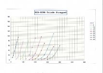
5894 is QQVO6-40; this is one of the few double beam tetrodes for which I have not prepared triode curves.
If you are intending to run these as beam tetrodes then driving them will be very easy - just download the curves from Frank's site.
If yoiu are planning to strap them as triodes, then somehow you will have to make triode curves; however they are very similar to 829B (I have tested them as triodes in the past) so in case it may be useful I have attached a set of 829B triode curves. I cannot upload Excel files so I have had to scan a set sorry about the scan quality - email me for the Excel if you wish.
Ra will be about 1k so for push-pull I would go for about 6k or so.
Many beam tetrodes/pentodes have considerabl capacitance when triode-strapped, so I suggest something that can pass a bit of current with lowish Ra: depending on the gain you require look at 12B4, 6BX7, 6BL7, 6463 and so on. ALternatively you could opt for a6SN7 cathode follower and the valve of your choice in front to get the voltage gain you need. You will need to swing in the region of 65v pk-pk.
I would not run 6-40s or 829s at more than about 35W Pa total.
Best of luck
7N7
Attachments
My intention is to run them in tetrode mode at about 300-450V B+ with my hammond at 4k3 or around 6k (using the 4ohm tap on my 6ohm speakers). 30-40W is super never needed any more. I hope for a fun project since I allready got all components including surplus transformers and chokes as well as driver tubes. Please email me your excel sheet at orion@otenet.gr
My best regards
Panos
My best regards
Panos
If your intention is to wire them up in fixed screen mode, then you won't be needing the triode curves. They have a common g2, so triode strapping necessitates paralleling the sections within the envelope, as well.
You'll be needing some sort of feedback to reduce output impedance, and distortion - either the "usual" type, by taking the output, and feeding it into a potential divider then injecting into the input valve's cathode, or maybe using some form of local feedback loop. This is an RF valve, so input capacitance should be small when run in fixed screen mode - this means that even when being driven by a high output impedance driver (such as a pentode), the bandwidth should not suffer too much.
You'll be needing some sort of feedback to reduce output impedance, and distortion - either the "usual" type, by taking the output, and feeding it into a potential divider then injecting into the input valve's cathode, or maybe using some form of local feedback loop. This is an RF valve, so input capacitance should be small when run in fixed screen mode - this means that even when being driven by a high output impedance driver (such as a pentode), the bandwidth should not suffer too much.
Well said Jason.
One of the reasons that I have not built beam tetrode or pentode amplifiers is that I cannot do the feedback mathematics. Even with my balanced line amplifiers, when it is supposed to be easy I have experienced dire and bizarre results - with the honourable exception of applying a little cathode feedback from the output transformer. So feedback and I do not get on.
The one thing that is most important to note with these valves is that they do get very hot; I prefer to have a small fan blowing on the QQVo3-20s and 7-50s that I am running. Without the fan the 3-20s get hot enough to melt the solder on the anode connectors. Now I use Fahnstock clips with nut-and-bolt connectors.
Incidentally, YL1071 had a precision envelope - not used on YL1070 its electronic equivalent - which was because Mullard/Philips came up with a close-fitting heatsink. As I wrote above, I would prefer to use finned anode connectors to protect the glass -to-metal seals
7N7
What do you lot use 12E1's for?
I found a load of 12E1's in the attic, I was going to use one for a regulated supply for an EL84 stereo (if I can get my head around how to use one in a circuit), but I see vague hints that they can be used for audio??
I found a load of 12E1's in the attic, I was going to use one for a regulated supply for an EL84 stereo (if I can get my head around how to use one in a circuit), but I see vague hints that they can be used for audio??
Yes I looked at these.
I never understood how to use beam tetrodes as output valves because I am unable to do the mathematics for feedback - any feedback experiments were disastrous.
However I did make triode curves for 12E1. It will work happily at 400V triode-strapped, but sadly it is not very linear, the curves closing up with the voltage. I suppose a carefully arranged p-p design might work. Otherwise it will have to be a 275V-max 3W single-ended "jazz" job with horn loudspeakers!
7N7
Edit: One thing I did use 12E1 for was as a big current sink beneath the cathodes of a 6528A in my 10W DC-coupled amplifier. This actually sounded quite good by the way.
Re: Re: Re: Other valves in my box of bits
Just reviewing this thread whilst looking for something else (it's raining again...).
I wondered how you are getting on with YL1071?
7N7
audiousername said:
I hope no one active in this thead is a member of that club... I'd much prefer YL1071 to any boring 300B!
Just reviewing this thread whilst looking for something else (it's raining again...).
I wondered how you are getting on with YL1071?
7N7
amperex 8624
I can't find a datasheet for these double-beam tetrodes I've bought. Can anyone help me? They look like my YL1070's..
I can't find a datasheet for these double-beam tetrodes I've bought. Can anyone help me? They look like my YL1070's..
I don't know what went wrong with the mail, but the content was pretty much going like this:
After reading a few of your postings on audioasylum
and diyaudio, it inspired me to try out a few tubes
myself; 3e29, 829b, 5894 and a number of its
equivalents and now I have ended up using the YL1070,
a truly great tube.
I have a couple of questions for you if you have the
time:
1.Do you know any good sources for buying YL1070 and
qqvo7/50 (haven't tried this one yet)? They tend to be
expensive...
2.Have you tried the YL1060 / 7854?
Thanks.
Well, I have always sung the praises of YL1071 (a 1070 with 13/26V heater). 5894 (QQVO6-40) is really just an 829B. Quite rare but a good compromise is QQVO7-50, which is a sort of "in-between").
YL1060 I have no experience.
Tell us a bit about how you are running the YL1070.
I recall that a few years ago there was someone in Holland or Germany that had some at reasonable prices. In theory, this kind of numbering ending with Zero is supposed to be a prototype, but there seem to be a few around.
7N7
Sorry for the five month late reply. 😱Originally posted by 7N7
I wondered how you are getting on with YL1071?
Unforunately life has been getting in the way and the valves and components have been stored away in a cupboard. Realistically, I can't see myself getting to them any time soon. I've actually been thinking of finding them a new home...
- Status
- Not open for further replies.
- Home
- Amplifiers
- Tubes / Valves
- 8233, 8116 & 6BZ6 valves - what are they good for?