YL1071s & friends pictured
Here's a nice snap of some of our friends complete with their relatives.
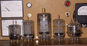
Left to Right: EEV QQVO3-20 (as used in my tweeter amplifier), YL1071 branded Philips, made in U.S.A. but in a Miniwatt box!, Mullard YL1150 (France), 8116 Amperex (U.S.A.) RCA 832.
They are waiting for something to happen in front of the QQVO7-50 Dashboard amplifier.
7N7
Here's a nice snap of some of our friends complete with their relatives.
Left to Right: EEV QQVO3-20 (as used in my tweeter amplifier), YL1071 branded Philips, made in U.S.A. but in a Miniwatt box!, Mullard YL1150 (France), 8116 Amperex (U.S.A.) RCA 832.
They are waiting for something to happen in front of the QQVO7-50 Dashboard amplifier.
7N7
Attachments
Re: 8116 Push Pull
Hi all
That 8116 Push Pull seems like a Fun Thing , Jason
Further developments and complications eagerly awaited 😉
cheers
audiousername said:Much more interesting than that boring SE stage that I posted yesteday. So interesting in fact that I don't actually know if it will work!
Hi all
That 8116 Push Pull seems like a Fun Thing , Jason
Further developments and complications eagerly awaited 😉
cheers
Re: Re: 8116 Push Pull
Thanks, Jan. It's nice to know someone is following 😉
7N7[/i] [B]Note: I might give the impression that I am flippant about safety - I assure you that I treat electricity with great respect and trepidation too when testing and strongly recommend that others do too[/B][/QUOTE] I'd never think that... I recently came across your article about the 813 amp from 1999 - seeing as you built that death-trap and survived shows you're obviously very careful! [QUOTE][i]Originally posted by slowmotion said:That 8116 Push Pull seems like a Fun Thing , Jason
Further developments and complications eagerly awaited 😉
Thanks, Jan. It's nice to know someone is following 😉
Complications
I am heartened to find out that I am not the first person to think of using a drive stage like the one pictured in the 8116 PP schematic. Patrick Turner has done something a little like this, among other things back in 1996 - so it should work.
In that schematic, the triode is doing the bootstrapping, instead of the pentode (in this case, the pentode is doing the amplifying), and there is local feedback from the output stage to the grid of the bootstrapping triode. The local feedback arrangement won't work so well if we use a triode for the bottom valve, because of its much lower ra would mess with the feedback arrangement.
Using something like this, we could get away using a single 8116/YL1071 (or 829B, 832A, QQV03-20A or whatever) as the output stage by operating them in fixed-screen (pentode) mode, despite the fact that the screen grid is common to both sections. Fool SE enthusiasts with a single output valve PP amp!
The simple version of the amp, and the sophisticated version. I much prefer the simple version - I am irrationally averse to ECC83/12AX7s...
I suppose DC coupling could be tried, it's just a matter of getting the output DC from the drive stage right... as long as it's stable. Though it will require a negative supply.
I am heartened to find out that I am not the first person to think of using a drive stage like the one pictured in the 8116 PP schematic. Patrick Turner has done something a little like this, among other things back in 1996 - so it should work.
An externally hosted image should be here but it was not working when we last tested it.
In that schematic, the triode is doing the bootstrapping, instead of the pentode (in this case, the pentode is doing the amplifying), and there is local feedback from the output stage to the grid of the bootstrapping triode. The local feedback arrangement won't work so well if we use a triode for the bottom valve, because of its much lower ra would mess with the feedback arrangement.
Using something like this, we could get away using a single 8116/YL1071 (or 829B, 832A, QQV03-20A or whatever) as the output stage by operating them in fixed-screen (pentode) mode, despite the fact that the screen grid is common to both sections. Fool SE enthusiasts with a single output valve PP amp!
The simple version of the amp, and the sophisticated version. I much prefer the simple version - I am irrationally averse to ECC83/12AX7s...
I suppose DC coupling could be tried, it's just a matter of getting the output DC from the drive stage right... as long as it's stable. Though it will require a negative supply.
There was an amplifier that used 829Bs as p-p beam tetrodes that was christened the "Cold War Amplifier"; unfortunately a search on Google failed to find it. The chap who made it was European but sadly I have forgotten his name!
QQVO3-20 will get very hot if run hard and 20W really is a bit optimistic; perhaps the rating was an "intermittent RF" one. Best to consider it as a 15W Pa device - and use it as an alternative to 2A3 (easier to drive though!).
As for DC coupling to the output valves, I use this in my tweeter amplifier and my 13E1 amplifier. These have been pretty reliable althought the 13E1 amplifier has been a bit temperamental lately but I have been using it for four years. It is important to have trimmers to adjust balance betweent he output valves and also to adjust the bias AND don't make my mistake: put the trimmers somewhere where you can get at them - i.e. on top of the amplifier. You will need some means od measuring; I like to use a centre-zero meter for the output valves and a milli-ammeter to monitor the output stage current. Clever folk could probably organise LEDs.
7N7
7N7 said:There was an amplifier that used 829Bs as p-p beam tetrodes that was christened the "Cold War Amplifier"; unfortunately a search on Google failed to find it. The chap who made it was European but sadly I have forgotten his name!
It was Remco Stoutjesdijk aka Ultranalog. It used 832As, but sadly the site has been pulled from the web following a very public stoush here. There is another project here (check out the solid state blue glow
 )
)7N7 said:QQVO3-20 will get very hot if run hard and 20W really is a bit optimistic; perhaps the rating was an "intermittent RF" one. Best to consider it as a 15W Pa device - and use it as an alternative to 2A3 (easier to drive though!).
shhh.... the 2A3 is a sacred device, unrivalled by any dirty triode-strapped pentode not even designed for audio amplification!
7N7 said:It is important to have trimmers to adjust balance betweent he output valves and also to adjust the bias AND don't make my mistake: put the trimmers somewhere where you can get at them - i.e. on top of the amplifier. You will need some means od measuring; I like to use a centre-zero meter for the output valves and a milli-ammeter to monitor the output stage current. Clever folk could probably organise LEDs.
Yep, it's also important to make sure that the grids of the output valves don't stick to B+ until the drivers start to conduct. This will result in excess current in the output valve during turnon which will probably destroy them eventually. An easy fix is using an IH valve rectifier for the B+ and SS diodes for B-.
EDIT: Fixed spelling of Remco's surname.
Blues
That's right: Remco; oh dear - a "stoush"!!
I meant to add into my message that I used a couple of 317 regulators in an attempt to keep the bias within limits. The -ve supply is unregulated so if the mains goes up as it often does then no harm can be done.
The amplifier to which you posted the link looks very smart and very nicely made; much better than most of my lash-ups, although my RCA acorn pre-amp is quite good but I have never made the power supply for it...
A bit of a cheat using blue LEDs under the 832s; he could have used some gassy 826s; I had some of these; they were very blue until I gave them a good cooking. 13E1s can be quite blue when new - I suspect that this is a common problem with larger glass-bottomed valves, although I have not had any problem with the double tetrodes - QQVO-XXX series or YL1071 - or 829/832.
Now completely off topic, the rather rare 7150, made by Ericsson is a high gm pure tetrode (makes a good triode by the way with mu of about 33) and lights up very nicely when run as a tetrode.
7N7
Other valvs in my box of bits
Attached is a list of the other valves in the box of stuff I got. Some seem to be RF (metal thingies, not glass) so are probably useless, but I dont really know.
If anyone can come up with anything interesting, let me know.
If anyone has any use for any of these, they are for sale - make me an offer on what you want.
Shane (Jack) Daniel
Number Quantity Additional info
7558 7
6442 20
8233 1
2J3A5 1
5654W 13 CV4010?
5670W 27
5814A 3
6AN5WA 2
6AQ4 1
6AQ4/7344 2
6BQ5 6
6BZ6 3 8639
8532W 13 6J4
CV132 7346 10
CV132 K/FE 7232 2 6HI (ITT)
CV378 2
CV4014/M8083 4
CV4015 8 6065 7614 CV4015 KB/QDD
CV4025 143/AD 3
CV424 KB/DF 2
EAC91 9
M8161 4 6065 7749 CV4015 BB/QDD
QQV03-20A 2
YL1370/6146B 3
8116 4
8233 6
Re: Other valves in my box of bits
Don't knock 'em. Actually, that's good advice whether valves are glass or metal. When I was young and ignorant, I trashed lots of stuff that I didn't recognise - don't repeat my mistakes. RF valves can be very useful for audio. You've got a whole lot of useful stuff there if you don't mind not being a member of the 300B SE club.
jack daniel said:Some seem to be RF (metal thingies, not glass) so are probably useless, but I dont really know.
Don't knock 'em. Actually, that's good advice whether valves are glass or metal. When I was young and ignorant, I trashed lots of stuff that I didn't recognise - don't repeat my mistakes. RF valves can be very useful for audio. You've got a whole lot of useful stuff there if you don't mind not being a member of the 300B SE club.
Hi Shane,
You're up early for Australia Day!
I hunted down datasheets for basically all the valve numbers you sent me in the spreadsheet. The CV132 (6H1) is a hexode, so it might not be so useful. The CV4025 is a double diode, and the 6442 is the little metal RF triode.
EDIT: That's strange, I've lost the CV number for the metal valve... oh... it's the CV3988 but it's not in the list... ergh...
Re: Re: Other valves in my box of bits
I hope no one active in this thead is a member of that club... I'd much prefer YL1071 to any boring 300B!
EC8010 said:if you don't mind not being a member of the 300B SE club.
I hope no one active in this thead is a member of that club... I'd much prefer YL1071 to any boring 300B!
audiousername said:Hi Shane,
You're up early for Australia Day!
I hunted down datasheets for basically all the valve numbers you sent me in the spreadsheet. The CV132 (6H1) is a hexode, so it might not be so useful. The CV4025 is a double diode, and the 6442 is the little metal RF triode.
EDIT: That's strange, I've lost the CV number for the metal valve... oh... it's the CV3988 but it's not in the list... ergh...
I was going to look some of them up but am just too fundamentally lazy. I thought that CV 3988 was E180F - or is that CV3998? (another pentode that makes a decent triode) but then I cannot find my book of CV numbers.
I do have an early WE baby klystron; I challenge anyone to make a decent audio stage with that - funny-looking thing; it has a sort of screw arrangement for tuning, so it's only intended to work at a set frequency (that's "set" not "SET"😉 ) .
If no-one minds me wandering off-topic again, I might post a picture of it - if I can find the little beggar.
7N7
7N7 said:I was going to look some of them up but am just too fundamentally lazy. I thought that CV 3988 was E180F - or is that CV3998? (another pentode that makes a decent triode) but then I cannot find my book of CV numbers.
Fundamentally lazy... 😀 No, actually I wasn't that fast in finding the datahseets, Shane sent me that list a few days ago. Silly me thought that he had the CV number for the RF metal triode in the list, but it was actually listed under its ordinary name (6442).
Yes, CV3998 is E180F, I have a few of these.
7N7 said:If no-one minds me wandering off-topic again, I might post a picture of it - if I can find the little beggar.
Pictures of valves are always great to look at 😀
Whoopsie
I made a mistake in the PP amp schematic I posted earlier. The grid leak resistors on V3 and V4 were inexplicably replaced with shorts, so the thing actually wouldn't work after all!
 WARNING The following schematic not only concerns push-pull amplification, it does not contain any triodes - not even triode-strapped pentodes, contains local negative feedback, some fifty-two parts, and even a little silicon. Possibly enough to give triode purists a severe case of apoplexy. It is a public holiday today, so I'm a little bored....
This is sufficiently crazy that I might actually build it though!
Any suggestions on how to allow balance between sections the of an 8116, or 829 or whatever I can get my hands on... There are no part values because I don't know what output valve will be in there yet. I would assume the sections would be fairly well matched since these double tetrodes were designed for this kind of operation though. The cathode is common to both sections, so I can't use a pot there to control the current between sections, but what about a pot at the cathodes of the input pentodes, or possibly even their screens?
Gary Pimm's PP47 and PP1624 amps are vaguely similar and use a DC servo to tackle the problem of DC drift, which is a nice solution. Unfortunately I lack the expertise to design or implement something like that at the moment.
I made a mistake in the PP amp schematic I posted earlier. The grid leak resistors on V3 and V4 were inexplicably replaced with shorts, so the thing actually wouldn't work after all!
WARNING The following schematic not only concerns push-pull amplification, it does not contain any triodes - not even triode-strapped pentodes, contains local negative feedback, some fifty-two parts, and even a little silicon. Possibly enough to give triode purists a severe case of apoplexy. It is a public holiday today, so I'm a little bored....This is sufficiently crazy that I might actually build it though!
Any suggestions on how to allow balance between sections the of an 8116, or 829 or whatever I can get my hands on... There are no part values because I don't know what output valve will be in there yet. I would assume the sections would be fairly well matched since these double tetrodes were designed for this kind of operation though. The cathode is common to both sections, so I can't use a pot there to control the current between sections, but what about a pot at the cathodes of the input pentodes, or possibly even their screens?
Gary Pimm's PP47 and PP1624 amps are vaguely similar and use a DC servo to tackle the problem of DC drift, which is a nice solution. Unfortunately I lack the expertise to design or implement something like that at the moment.
Attachments
Is this how the Quad II cheat is implemented? I was trying to draw in a pot between R20 and R21 for fine tuning the DC current through each section of the output valves, but I don't know how to draw pots in LTSpice...
I had a look at the Quad II schematic here. A much more elegant design than this!
I had a look at the Quad II schematic here. A much more elegant design than this!
Attachments
Yes, that's it, although you probably don't need R26 and R27. Alternatively, you could do something clever involving neons to really hold g2 at a constant voltage.
Something Clever
I spent a little while thinking about the differential pair with pentodes. The cathode current is the sum of the anode and screen currents, and it is the total cathode current which we hold constant, so maybe the varying screen currents can wreak a little havoc.
So, using EC's idea of a VR valve, we don't want to send it all the way down to the B-, that would require too many in series and wouldn't be particularly clever or original.
Let's try sitting the VR on the cathodes, and feed it with a CCS. So, now the screen voltage is locked, but not only that - the sum of the screen current plus the VR valve current is constant (they're fed with a CCS). Hmmm... clever indeed!
Unfortunately I can't claim credit for it - it's based on crumbs from EC and a very large crumb from Gary Pimm.... I got rid of the semiconductor CCS for the diff pair; using a deeper negative supply lets one use more glass: very important. The chopping and changing has left the part numbers following no known logical pattern.
EDIT: Now the screen supply for the output valve isn't up to scratch - too boring. Oh well....
Not so clever
I made a mess of things and had to pull that last schematic off because of too many mistakes!
I think it's fixed now.
Does replacing R19 and R20 with a pot would allow some degree of control over DC bias or does V3 and V4 mess things up somehow? I probably know the answer but I'm not thinking straight right now.
Attachments
You might want to borrow another of Gary Pimm's ideas and provide some adjustment at g2 to set DC balance. If you apply a higher voltage to g1 of the pentode CCS, then you can have a much larger cathode resistor, which will be multiplied by the mu of the valve to make a better CCS.
- Status
- Not open for further replies.
- Home
- Amplifiers
- Tubes / Valves
- 8233, 8116 & 6BZ6 valves - what are they good for?