222mVbe is still not turned on.
But is is ~ 3times higher than previous.
Are the outputs undamaged?
Output should not be demaged 🙂 I ordered them not to do so! heheh
OK
"I changed drain resistor yesterday, to 1,8R.
Now upper is 362mV, lower 367mV, source 3,3R have 622mV.
Base/emitter power transistors 222mV and 505mV."
When i "plug in" dc servo, soldier 1k resistor on opamp out. Output transistors have Vbe 379mV and 348mV, dc out near 0 or 0🙂
what voltage is the DC servo opamp putting out?
How close is it getting to it's supply rail?
Changing to the 1k instead of the 1k2 increases slightly the amount of correction available, but that also means a little more current.
How close is it getting to it's supply rail?
Changing to the 1k instead of the 1k2 increases slightly the amount of correction available, but that also means a little more current.
"current dumping" ?
I see a CCS loaded SE driver into a complementary push pull output stage, with a nonsense tempco on the driver that can never compensate for changes in output stage temperatures.
Current Dumping Technology | QUAD | the closest approach to the original sound
And that's it 🙂When i "plug in" dc servo, soldier 1k resistor on opamp out. Output transistors have Vbe 379mV and 348mV, dc out near 0 or 0🙂
With 1k there will be slightly lower gain, but OK
Other option is to make inverting integrator (inverting dc servo) and connect it through 470k-820k resistor to amp input (pin 7), but with this solution like on schematic expensive 2.2uF input capacitor can be eliminated.
For security reasons I'd never eliminate an input capacitor. You'll never be sure if your preamp has an output cap, and if so, if it is not leaky.
Best regards!
Best regards!
"current dumping" ?
I see a CCS loaded SE driver into a complementary push pull output stage, with a nonsense tempco on the driver that can never compensate for changes in output stage temperatures.
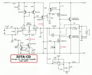
If you stare at the schematic long enough it makes sense. Notice the two output paths. The IRF9530 is a CCS. The IRF530 is the current dumping transistor. These are the output devices under light load. On higher current peaks the 2SC3264 and the 2SA4302 become active due to the voltage drop across the two 1.5R source resistors on the mosfets.
How does one increase the number of output pairs in this design, in order to make it capable of 4 ohms loads and/or higher rails voltages? Is it done the usual way, i.e. by providing current balancing emitter resistors? Is this possible at all?
Best regards!
Best regards!
I think you'd be starting from scratch with a new design to add output devices. This whole amp looks very part dependent. VZaichenko's TubSoMo would be a better choice for a scale-able design.
There are a couple other versions of tube hybrids from Valery and Borys has done some nice ones as well. I'll see if I can locate some info on them.
Thanks! This TubSuMo seems to be a rather cool design, because obviously there's no need for a separate highish voltage supply for the tube LTP. What are the rail voltages?
Best regards!
Best regards!
Last edited:
The TubSoMo is a great design. It was originally tuned for +/-70V rails but Valery has hooked it to his NS-OPS at +/-50V rails and it ran very nicely. The superpair VAS section can be a bit tricky with some output designs though. It didn't run nicely with Ostripper's Slewmaster output.

Update
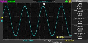
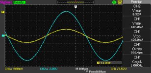
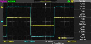
I was sure that there is low current to drive output transistors.
Increasing resistors between irf to 2ohm, mekes better sin wave, and square wave doesn't have overshoot. I think i will increase it to 2,2 ohm and leave i that way.
I was sure that there is low current to drive output transistors.
Increasing resistors between irf to 2ohm, mekes better sin wave, and square wave doesn't have overshoot. I think i will increase it to 2,2 ohm and leave i that way.
Attachments
I was sure that there is low current to drive output transistors.
Increasing resistors between irf to 2ohm, mekes better sin wave, and square wave doesn't have overshoot. I think i will increase it to 2,2 ohm and leave i that way.
Hello everyone!
Someone built the IOTA CD? It works in a simulator but a lot of FETs dissipate. I think the layout is not good!
- Status
- Not open for further replies.
- Home
- Amplifiers
- Solid State
- 80W Hybrid Audio Amplifier!