Who says anyone will be pretending, don't know where you got that? People have different beliefs and different needs to believe they know things with certainty. People prefer experts who are certain, those are the ones they tend to trust. That's true even if the experts believe they know more than they actually do.
Of course! I want proclaimed experts to be very assertive.
But I still want to be able to form my own opinion from multiple sources.
I'm sure this is what you want as well.
While working on this project, I am starting to understand that there are three main kinds of audiophiles out there:
1. The ones who only care about objective measurements.
2. The ones who only care about subjective sound quality.
3. The ones who try to reconcile both approaches.
As if often the case, you understand wrong. Unlikely Chris would want to claim to be an audiophile. And Jam's list of the types of audiophiles is very different from yours.
Of course! I want proclaimed experts to be very assertive.
Because you are uneducated. Read Tetlock and Haidt. I can't teach you everything in textual sound bytes. It doesn't work that way. You have to do some homework.
Because you are uneducated. Read Tetlock and Haidt. I can't teach you everything in textual sound bytes. It doesn't work that way. You have to do some homework.
Obviously... I'll get back to the textbooks then. Good night my friend.
Because you are uneducated. Read Tetlock and Haidt. I can't teach you everything in textual sound bytes. It doesn't work that way. You have to do some homework.
Relax, you don't need to be so serious, it's just audio. I'm sure he is quite educated as well...
Looks good.Of course, and they don't on the schematic. Did I miss something?
Obviously. And that's the point of having these on a separate board. That way, we can build a board with AD817 (like what AKM does on its evaluation board) and with AD825 (like I am suggesting).
Building these add-on boards is easy and cheap. Having the ability to test the whole system with different boards like that is the only way I know to get the best SQ we can get, in a very iterative fashion, without having to pay for many AK4499 DAC chips.
If you know a better way of going about this, I'm all ears... 🙂
As discussed, this is a good strategy for tweaking down the track.
BUT - on the evaluation board, all the grounds join at the DAC chip. It's worth studying the grounds carefully on the eval brd. So the super regs
grounds should be separate, only joining where they hit the main DAC board, close to the DAC chip.
PS, I've been away and off the thread, don't know whether you have discussed this.
I get it now!
CLKS0..2
CLKS0 to select the crystal.
CLKS1 to select division.
CLKS2 to select external clock.
All these come from the USB board (aka Plate), through the PSU board, then are sent to the Clock board.
I'm really sorry that I don't have a proper block diagram or CAD model for all this, but it's changing all the time, and it's easier to keep it in my head for now. That being said, all prior posts should be consistent with this design. But I understand that it's virtually impossible for anyone to keep track of all the changes. Therefore, the schematic should be considered as the one and only source of truth at any point in time.
Once things settle down a bit, I'll set the GitHub repository up, so that anyone interested can keep track of all changes in a much more reliable manner.
That's a great idea. It's probably a welcome slight diversion if you are getting
overwhelmed with everyone barking at you.
 haha 🙂
Take your time, there's a lot to know and nobody knows it all (despite what
they may think).
I talked to Jam yesterday, and he is moving to Altium CircuitStudio, which is the EDA tool that I am currently using (I really love it btw). Knowing that Chris is using Altium Designer, this should make it a lot easier for all parties involved to keep track of the project and its design artifacts.
I'm thinking of going that way myself. Not getting on that well with
Design Spark. My experience with CAD design systems is you get on with
them or you don't.
T
Looks good.
As discussed, this is a good strategy for tweaking down the track.
BUT - on the evaluation board, all the grounds join at the DAC chip. It's worth studying the grounds carefully on the eval brd. So the super regs
grounds should be separate, only joining where they hit the main DAC board, close to the DAC chip.
PS, I've been away and off the thread, don't know whether you have discussed this.
We have discussed this just a little bit. I need to study it a lot more. Thank you Terry.
That's a great idea. It's probably a welcome slight diversion if you are getting
overwhelmed with everyone barking at you.
Take your time, there's a lot to know and nobody knows it all (despite what
they may think).
I'm thinking of going that way myself. Not getting on that well with
Design Spark. My experience with CAD design systems is you get on with
them or you don't.
T
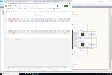
Here is a great comparison of the features between Altium Designer and CircuitStudio.
So far, I have not missed a single feature.
Down the road, I expect that I'm going to need non-circular holes and export to STEP. Both features are only available on Altium Designer. But these are things that are needed only at the end of the process, therefore I could work with someone who has Altium Designer and could generate the production files for me.
I’ve never tried to open or import CS files but I would guess it’s easily done if not the exact same file format. I can give it a try for you when you’re ready.
I’ve never tried to open or import CS files but I would guess it’s easily done if not the exact same file format. I can give it a try for you when you’re ready.
Thanks a lot Chris. I'll email you some files as soon as I have a complete schematic for the DAC board.
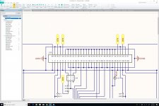
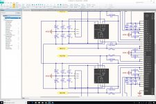
Updated Pinout for PSU-to-DAC Connectors
The connectors linking the DAC board to the PSU board have been updated in order to provide just what we need and to better isolate circuits from each other.
The connectors linking the DAC board to the PSU board have been updated in order to provide just what we need and to better isolate circuits from each other.
Attachments
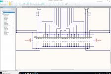
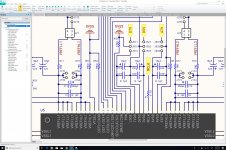
Clock Board
The clock board will be mounted on the DAC board using the J64 and J65 connectors. J64 are Mill-Max machined pin sockets, while J65 is an Amphenol coaxial P-SMP connector. These don't come cheap, but they should help reduce jitter. The clock has its own LDO regulator board, mounted on the DAC board through J61..63. We could try to mount the regulator directly on the clock board, but I am trying to reuse the regulator boards that we will design for other parts of the system, and I am not convinced that it will make much of a difference in the end.
The clock board will be mounted on the DAC board using the J64 and J65 connectors. J64 are Mill-Max machined pin sockets, while J65 is an Amphenol coaxial P-SMP connector. These don't come cheap, but they should help reduce jitter. The clock has its own LDO regulator board, mounted on the DAC board through J61..63. We could try to mount the regulator directly on the clock board, but I am trying to reuse the regulator boards that we will design for other parts of the system, and I am not convinced that it will make much of a difference in the end.
Attachments
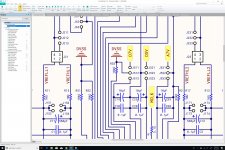
Super Regulator Board
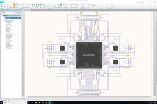
There is quite a lot going on here. J21 and J23 are two of the four 4-pin connectors used to mount the Super Regulator board with the four Jung/Didden circuits (the other two are J22 and J24). Next to them, we have J211..213 and J231..233, which are used to mount two LDO regulators (with another pair on the other side of the DAC board). The regulator boards will take 17V down to 15V, while the Jung/Didden circuits will give us the four VREFs required by the DAC chip.
There is quite a lot going on here. J21 and J23 are two of the four 4-pin connectors used to mount the Super Regulator board with the four Jung/Didden circuits (the other two are J22 and J24). Next to them, we have J211..213 and J231..233, which are used to mount two LDO regulators (with another pair on the other side of the DAC board). The regulator boards will take 17V down to 15V, while the Jung/Didden circuits will give us the four VREFs required by the DAC chip.
Attachments
Connectors to XLR Board
At this point, the only thing missing on the DAC board are the four connectors to the XLR board. We will add these sometime at the end of next week. I'll be on the road for most of the week, so not much will happen on the audio front for me during that time.
At this point, the only thing missing on the DAC board are the four connectors to the XLR board. We will add these sometime at the end of next week. I'll be on the road for most of the week, so not much will happen on the audio front for me during that time.
Attachments

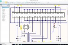
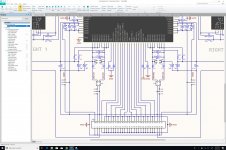
May I ask how come Port 100 on the eval board has 12 pins total, 6 signals and 6 grounds, yet there are more than 6 green clock and data signals on the South connector?
Also, how do the clock selection bits get from the USB_board/MCU to the clock board?
Also, how do the clock selection bits get from the USB_board/MCU to the clock board?
Attachments

- Home
- Source & Line
- Digital Line Level
- 8 × AK5578EN + 8 × AK4499EQ ADC/DAC Boards