It's definitely a science, but it's a real pain and a lot of work to figure out the exact optimal solution. Often, rules of thumb are enough to get you close.
My point, exactly!
To be clear: I'm not advocating for one way or another. Ideally, you walk down both tracks at the same time.
And this dichotomy is what makes the craft so very interesting: it's both art and science. That's what I love about it.
And it's up to anyone to set the dial at the level they're most comfortable with.
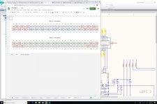
Updated PSU to DAC Connector Pair
Here is the updated connector pair between the PSU Board and the DAC Board.
In a totally-unexpected way, it's becoming more and more symmetrical.
Here is the updated connector pair between the PSU Board and the DAC Board.
In a totally-unexpected way, it's becoming more and more symmetrical.
Attachments
Last edited:
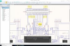
Connectors for Super Regulator Board
Here are the four connectors for the four corners of the 4-channel Super Regulator board. Currently, this assumes that the 17V to 15V regulation (with 1, 2, or 4 LT3042 LDOs) happens on the Super Regulator board itself. That being said, I think we could do it using four regulator boards mounted on the DAC board, really close to the four 4-pin sockets used to connect the Super Regulator board. This would allow us to reuse the LT3042 regulator boards that we will use for the rest of the DAC board. This change to the schematic should be really straightforward if we decide to go down that path.
Here are the four connectors for the four corners of the 4-channel Super Regulator board. Currently, this assumes that the 17V to 15V regulation (with 1, 2, or 4 LT3042 LDOs) happens on the Super Regulator board itself. That being said, I think we could do it using four regulator boards mounted on the DAC board, really close to the four 4-pin sockets used to connect the Super Regulator board. This would allow us to reuse the LT3042 regulator boards that we will use for the rest of the DAC board. This change to the schematic should be really straightforward if we decide to go down that path.
Attachments

Here is the updated connector pair..
All you need in the way of digital audio connections are the same as shown for Port 100 on page 3 of the eval board manual. I would suggest to try to lay them out on a connector as they do on the eval board.
All you need in the way of digital audio connections are the same as shown for Port 100 on page 3 of the eval board manual. I would suggest to try to lay them out on a connector as they do on the eval board.
I don't think so. What my connectors are for is the mezzanine board that will have the four Jung/Didden Super Regulators, which are our alternative implementation for what is found on page 58. They will use the AD825 instead of the AD817. You can see J21..24 on this layout. Yes, I know, it's a lot of boards... But if we want the right level of power regulation within such a tight form factor, I do not know any way around it...
Attachments
Last edited:
The Jung regulators don't need digital audio signals, in fact those signals should not be stubbed out to where they will not be used. It can only distort the RF waveforms.
If you change the opamp for the reference voltage supply, the dac will probably sound different. Simply a consequence of zero PSRR for that circuit, so you hear the power supply to the extent it has a sound. You might want to test out the other opamp in the regulator first to see how you like it.
See. I didn't wait for you to fail.
Also, it is almost inevitable that Chris and I will disagree at some point, what then?
Last edited:
The Jung regulators don't need digital audio signal, in fact those signals should not be stubbed out to where they will not be used. It can only distort the RF waveforms.
Of course, and they don't on the schematic. Did I miss something?
If you change the opamp for the reference voltage, the dac will probably sound different. Simply a consequence of zero PSRR for that circuit, so you hear the power supply to the extent it has a sound. You might want to test out the other opamp in the regulator first to see how you like it.
Obviously. And that's the point of having these on a separate board. That way, we can build a board with AD817 (like what AKM does on its evaluation board) and with AD825 (like I am suggesting).
Building these add-on boards is easy and cheap. Having the ability to test the whole system with different boards like that is the only way I know to get the best SQ we can get, in a very iterative fashion, without having to pay for many AK4499 DAC chips.
If you know a better way of going about this, I'm all ears... 🙂
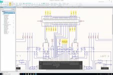
I was referring to all the green pins on the south connector. Where does that go?
If you have the crystal clocks there, that doesn't mean all those other signals come from there, they don't. They come from your USB interface.
You will need at least one signal to wherever the crystal clocks are to select the one to use. The number of signals depends on the number of clock frequency choices. The signal(s) will come from the USB interface. What have you named that signal or those signals?
Last edited:
Also, it is almost inevitable that Chris and I will disagree at some point, what then?
Great question! I'll make a reasonably-educated guess. You just have to trust that I will never play favorites...
At the end of the day, if it does not make sense to me, it's a non-starter.
And look at our track record so far: it might take me some time to understand what you or Chris write, but eventually, I usually find a way to take your input into consideration (or so I like to believe). Of course, I keep pushing my crazy agenda, but the value of the project comes from all the trade-offs that we have to make in order to reconcile multiple equally-valid viewpoints.
I was referring to all the green pins on the south connector. Where does that go?
If you have the crystal clocks there, that doesn't mean all those other signals come from there, they don't. They come from your USB interface.
Green pins? I see a lot of blue and yellow. But I might be color blind. Can you send an annotated screenshot by any chance? This would help clear any confusion. Thanks!
If you have the crystal clocks there, that doesn't mean all those other signals come from there, they don't. They come from your USB interface.
All the clock pins are on the North side, and I have yet to put the connectors for the clock mezzanine board. I hope to do that sometime tomorrow.
Attachments
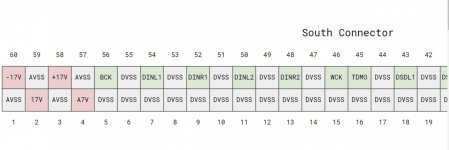
No green?
Oh, I see. Yes, these come from the PSU board, which has pass-through pins/circuits for USB circuits.
So, what about these?
You will need at least one signal to wherever the crystal clocks are to select the one to use. The number of signals depends on the number of clock frequency choices. The signal(s) will come from the USB interface. What have you named that signal or those signals?
I get it now!
CLKS0..2
CLKS0 to select the crystal.
CLKS1 to select division.
CLKS2 to select external clock.
All these come from the USB board (aka Plate), through the PSU board, then are sent to the Clock board.
I'm really sorry that I don't have a proper block diagram or CAD model for all this, but it's changing all the time, and it's easier to keep it in my head for now. That being said, all prior posts should be consistent with this design. But I understand that it's virtually impossible for anyone to keep track of all the changes. Therefore, the schematic should be considered as the one and only source of truth at any point in time.
Once things settle down a bit, I'll set the GitHub repository up, so that anyone interested can keep track of all changes in a much more reliable manner.
I talked to Jam yesterday, and he is moving to Altium CircuitStudio, which is the EDA tool that I am currently using (I really love it btw). Knowing that Chris is using Altium Designer, this should make it a lot easier for all parties involved to keep track of the project and its design artifacts.
Attachments
Last edited:
Great question! I'll make a reasonably-educated guess. You just have to trust that I will never play favorites...
What if I can demonstrate I am right if you come here to Auburn, but a debate between Chris and me will make you think Chris is right?
Thing is, debate doesn't lead to scientific truth, it only leads to the kind of truth that is used in politics and law. Its about who tells the best story.
Oh, I see. Yes, these come from the PSU board, which has pass-through pins/circuits for USB circuits.
So, what about these?
The USB board connects to the power supply board before the dac board?
Hmmm. Where else to those clock lines go, to every possible module location on the plate?
What if I can demonstrate I am right if you come here to Auburn, but a debate between Chris and me will make you think Chris is right?
Thing is, debate doesn't lead to scientific truth, it only leads to the kind of truth that is used in politics and law. Its about who tells the best story.
There is a really easy answer to that: you might go with one set of add-on boards, and Chris might go with another one. That is the whole point of having a modular design. I do not pretend to know what the truth is, and I won't listen to anyone pretending to know the truth either. It's all a matter of perspective.
If you and Chris can be happy with the core DAC board and your own sets of add-on board, this is what I would call a major success for the overall project. Ponder that for a minute or two. Then ask yourself the following question: what can we do to improve the proposed modular architecture in order to increase the likelihood of such an outcome.
Now, one could say that a modular design goes against the goal of designing the best-sounding DAC. I respect this position, and anyone holding it is wasting his/her time reading this thread.
Last edited:
The USB board connects to the power supply board before the dac board?
Hmmm. Where else to those clock lines go, to every possible module location on the plate?
That is a really good question!
My poor answer is "yes". And I realize that it might mean that we have an antenna problem.
Hmmm... I'll have to think about that one.
Thank you for bringing that one up Mark. This is really good stuff...
Last edited:
I do not pretend to know what the truth is, and I won't listen to anyone pretending to know the truth either.
Who says anyone will be pretending, don't know where you got that? People have different beliefs and different needs to believe they know things with certainty. People prefer experts who are certain, those are the ones people tend to trust. That's true even if the experts believe they know more than they actually do.
Last edited:
The Three Kinds of Audiophiles
While working on this project, I am starting to understand that there are three main kinds of audiophiles out there:
1. The ones who only care about objective measurements.
2. The ones who only care about subjective sound quality.
3. The ones who try to reconcile both approaches.
I have an equal amount of respect for all three populations, and one of the goals of this project is to provide a platform that can make it easier for every member of these communities to fine-tune a system according to their own preferences.
The third category believes in the benefits of a scientific approach driven by proper instrumentation, yet recognizes the fact that contemporary science is only a crude approximation for how the human ear and brain work. I like to believe that I belong to that group. That being said, I commend members of the first community for all their hard work, and I like to hang out with members of the second community for their expert advice and their refined language. Members of both communities help me become a better member of the third.
Any audiophile should decide which community he/she belongs to, and how he/she can make a meaningful contribution to the craft.
Last edited:
- Home
- Source & Line
- Digital Line Level
- 8 × AK5578EN + 8 × AK4499EQ ADC/DAC Boards