Does anyone have any experience with...
Nope. Don't know how they sound. The reason for using MELF in the first place rather than something like Susumu SMD resistors is because they are alleged to sound better (according to some testing done by Jam and someone else in the past). Perhaps smaller voltage coefficients or maybe less differential thermocouple effects if end caps are not at matched temps. Vishay has a reasonably good reputation for quality, too. Be interesting to see if anyone else has an opinion on different brands/types.
Nope. Don't know how they sound. The reason for using MELF in the first place rather than something like Susumu SMD resistors is because they are alleged to sound better (according to some testing done by Jam and someone else in the past). Perhaps smaller voltage coefficients or maybe less differential thermocouple effects if end caps are not at matched temps. Vishay has a reasonably good reputation for quality, too. Be interesting to see if anyone else has an opinion on different brands/types.
Thanks!
So far, I'm using Vishay for all resistance values but 10Ω.
And I must assume that the lower the resistance value, the higher the tolerance we can bear (please correct me if this is incorrect).
...I must assume that the lower the resistance value, the higher the tolerance we can bear (please correct me if this is incorrect).
Acceptable tolerance depends on what the resistor is being used for, not its value in ohms. I/V feedback resistors and differential summing stage resistors should be well matched to help minimize common mode distortion, for example.
Acceptable tolerance depends on what the resistor is being used for, not its value in ohms. I/V feedback resistors and differential summing stage resistors should be well matched to help minimize common mode distortion, for example.
Got it!
Rated Voltage
From Ott's book:
"For maximum life, aluminum electrolytic capacitors should be operated at between 80% and 90% of their rated voltage. Operating at less than 80% of their rated voltage does not provide any additional reliability."
This answers one of the questions I had about using a capacitor rated at 6.3V within a 5V circuit. The answer is that it's totally okay.
Here you go. Nothing on the motherboard to show.
My understanding is that these are the C3, C11, C29_1, and C89 220µF capacitors.
And as far as I can tell C_X1, C_X2, C_X3, C_X4, C_X5, C_X6, C_X7, and C_X8 are not populated on the evaluation board.
Also, I assume that only C6, C15, C35, and C90 need to be as large as possible, while C3, C11, C29_1, and C89 can remain at 220µF.
Please let me know if you see it differently.
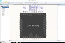
North Side
Here is the North side of the mezzanine board for the AKM evaluation board.
Trying to keep it as clean as possible...
Now working on the West side.
Also, I am currently sticking to the designators used for the evaluation board, but they're totally non-sensical, so when I'm done with the schematic, I'll replace them with more rational designators, but I'll make sure to provide a lookup table on the project's spreadsheet.
Attachments
Last edited:
External connections for things like TVDD and DVDD?
Also, although I would leave space for two 1200uf Reference Voltage caps for each channel, initially I would populate them with the same values as used on the evaluation board. For one thing, you haven't performed listening tests on two channels of the eval board with those changes to see if you can make it work.
Did you figure out where the 8pf caps go?
Is R1 actually 5.1 ohms or 51 ohms? (Just checking 🙂 )
Which are you calling the North side? You don't show any pin numbers on AK4499, or CN# numbers relative to eval board layout.
Last edited:
External connections for things like TVDD and DVDD?
Will be added once I get a better sense of how many headers are needed on the board. I need an outline of the schematic first.
Also, although I would leave space for two 1200uf Reference Voltage caps for each channel, initially I would populate them with the same values as used on the evaluation board. For one thing, you haven't performed listening tests on two channels of the eval board with those changes to see if you can make it work.
Yes, I'll do a lot of listening tests with different capacitors with the Evaluation Board before ordering any PCB. All I want at this point is a schematic so that I can start populating the PCB layout to make sure that everything will fit. If it does not, the whole design has to be redone, and no amount of listening will fix that.
I really hope that everything will fit...
Did you figure out where the 8pf caps go?
Not yet. Did you?
Is R1 actually 5.1 ohms or 51 ohms? (Just checking 🙂 )
Definitely 5.1Ω. I measured it. Even though I got a 5.4Ω reading, but my ohmmeter might be in need of some calibration.
Which are you calling the North side? You don't show any pin numbers on AK4499, or CN# numbers relative to eval board layout.
Pins 97 through 128. I refer to it as the North side in relation to the schematic of page 59 in the evaluation board's manual. I kept the same orientation in order to make it easier to read when going back and forth between the two version of the schematic. Also, when printed on a letter page in landscape format, it will fit better because of the I-V circuits, which take quite a bit of space on the page. And I do not display the pin numbers on this schematic because they're not really useful. There cannot be any confusion with the pin names and the dot at the top left.
I am planning to spend so much time looking at that schematic that I want it to be as streamlined and readable as possible. AKM's gives me a headache everytime I look at it...
Last edited:
C_X6 and some other locations have an SMD diode soldered across the vias (on my eval board anyway). How are you accounting for that?
Definitely 5.1Ω. I measured it. Even though I got a 5.4Ω reading, but my ohmmeter might be in need of some calibration.
What is the residual resistance of your test leads?
Definitely 5.1Ω. I measured it. Even though I got a 5.4Ω reading, but my ohmmeter might be in need of some calibration.
Just recalibrated the ohmmeter, and I still get a 5.4Ω reading... 5.9% deviation from the spec. Not so great...
I guess we'll be fine with a 1% part...
What is the residual resistance of your test leads?
0.1 Ω to 0.5 Ω... This is where the variance must come from.
Thanks!
In any case, 5.1 Ω is what we're looking at.
C_X6 and some other locations have an SMD diode soldered across the vias (on my eval board anyway). How are you accounting for that?
You're right! C_X2, C_X3, C_X6, and C_X8 do.
But C_X1, C_X4, C_X5, and C_X7 are open...
Man, my level of trust for this schematic has gone way low...
Great catch Mark. Thank you.
How can we figure out which diode should be used?
How can we figure out which diode should be used?
Didn't you already ask Chris719 about them and he suggested a substitution?
Original part number seems to be on the schematic.
Did you figure out where the 8pf caps go?
Actually, yes. I'm pretty sure they are the 180pF capacitors, mounted really close to the OpAmps.
C8, 9, 19, 20, 56, 57, 58, 59.
So, 8 was not pF, unless the schematic is wrong.
My Fluke 116 can't measure them (or I'm using it wrong). You might have more luck with your equipment.
Didn't you already ask Chris719 about them and he suggested a substitution?
Original part number seems to be on the schematic.
No, it was for the rotary encoder circuit.
And the schematic shows capacitors instead of diodes for these designators...
DB2132000L as shown on the schematic?
I thought you asked what they were for and Chris said something like, 'maybe for reverse voltage protection, you probably don't really need them?'
I thought you asked what they were for and Chris said something like, 'maybe for reverse voltage protection, you probably don't really need them?'
Last edited:
Nope. Don't know how they sound. The reason for using MELF in the first place rather than something like Susumu SMD resistors is because they are alleged to sound better (according to some testing done by Jam and someone else in the past). Perhaps smaller voltage coefficients or maybe less differential thermocouple effects if end caps are not at matched temps. Vishay has a reasonably good reputation for quality, too. Be interesting to see if anyone else has an opinion on different brands/types.
They aren't any better, they are just round. However, there is nothing wrong with them.
DB2132000L as shown on the schematic?
I thought you asked what they were for and Chris said maybe for reverse voltage protection, you probably don't really need them?
I forget, I'd have to go back and take another look.
Last edited:
- Home
- Source & Line
- Digital Line Level
- 8 × AK5578EN + 8 × AK4499EQ ADC/DAC Boards