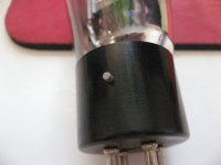
The 71A has an UX4 base, I've never used it before but I believe it doesn't have a 'collar' so to speak. Perhaps in the old days some had?
The 71A has an UX4 base, I've never used it before but I believe it doesn't have a 'collar' so to speak. Perhaps in the old days some had?
Yes.. I've got a few of the old style sockets here. The tubes twist in the base and lock.
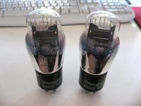
71A is noted for having misaligned filaments. (I've got more than a few useless ones for this reason) Check yours to make sure that the filaments are relatively equidistant from both sides of the grid. You can do this by looking carefully down from the top making note that the curvature of the dome may be misleading.
Last edited:
71A is noted for having misaligned filaments. (I've got more than a few useless ones for this reason)
Not totally useless. They will amplify. An OK regen radio could be made.
Not totally useless. They will amplify. An OK regen radio could be made.
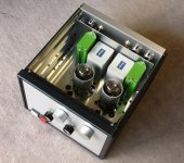
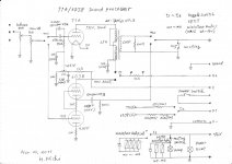
A 71A / 6DJ8 switchable sound processer was built yesterday. Combination of 71A and line transformer NP-8 ex-Tango works nicely.The primary coil of NP-8 was connected in parallel, so its impedance ratio changed to 2.5Kohm from 10Kohm , and eventually the transformation ratio has become 1:0.49. This solution fits to a low amplification factor 3 of 71A.
Incidentally the thread of #26 in this forum was of informative and valuable for me.
Operating condition of 71A:
Plate voltage: 122V
Plate current: 10mA
Grid bias: -26V
Sound impression:
Good in transparency on 71A, while wider range on 6DJ8-SRPP.
There was no significant differnce between them.
However I would rather wait for a month or so for a overall evaluation.
Attachments
Wise. It usually takes me a month to know if something stays or goes.However I would rather wait for a month or so for a overall evaluation.
Looks well built. Schematic?
I bought a pair of 71A few months ago and I don't know what to do with it.
Possibly it would be good to use them for the line amp.
Johnny
Possibly it would be good to use them for the line amp.
Johnny
Wise. It usually takes me a month to know if something stays or goes.
Looks well built. Schematic?
Thank you for your interest to my sound processor.
I shall upload the schmatics as soon as I finished drawing.
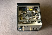
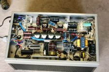
Attached is a bottom view of 71A sound processor.
Attachments
I bought a pair of 71A few months ago and I don't know what to do with it.
Possibly it would be good to use them for the line amp.
Johnny
Also you could build a 71A SE amp, in case you have a high sensitive SP system.
It was a fantastic sound, though the output power was only 0.9W.
I'm going to use my 71As for a electrostatic headphone direct drive amp! (I have 9 pieces of them now total.)
If I weren't going ESL, I'd build a regular headphone amp. Single ended, direct coupled, with mu follower 27 driving!
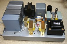
H.Michi, great work! What is the purpose of the metal 'tube' around the 71As?
Now that I have 9 71As (RCA, Tung-Sol, Westinghouse, Raytheon), I can see that the ST types all seem to have practically identical construction, with production dates over 10 years apart. Perplexing. Perhaps they were in reality made by only a few number of factories, then labeled for different brands. The globe types have a bit different construction.
I'm a bit worried about microphonics, many of them ring like a bell when I put them next to my ear and flick with a fingernail.
If I weren't going ESL, I'd build a regular headphone amp. Single ended, direct coupled, with mu follower 27 driving!
H.Michi, great work! What is the purpose of the metal 'tube' around the 71As?
Now that I have 9 71As (RCA, Tung-Sol, Westinghouse, Raytheon), I can see that the ST types all seem to have practically identical construction, with production dates over 10 years apart. Perplexing. Perhaps they were in reality made by only a few number of factories, then labeled for different brands. The globe types have a bit different construction.
I'm a bit worried about microphonics, many of them ring like a bell when I put them next to my ear and flick with a fingernail.
I'm going to use my 71As for a electrostatic headphone direct drive amp! (I have 9 pieces of them now total.)
If I weren't going ESL, I'd build a regular headphone amp. Single ended, direct coupled, with mu follower 27 driving!
H.Michi, great work! What is the purpose of the metal 'tube' around the 71As?
Now that I have 9 71As (RCA, Tung-Sol, Westinghouse, Raytheon), I can see that the ST types all seem to have practically identical construction, with production dates over 10 years apart. Perplexing. Perhaps they were in reality made by only a few number of factories, then labeled for different brands. The globe types have a bit different construction.
I'm a bit worried about microphonics, many of them ring like a bell when I put them next to my ear and flick with a fingernail.
The purpose is to seal electrostatic noise as well as shielding direct coupling between two tubes. Additionally suppressing air-borne vibration is achievable.
Mechanical osillation (around 2kHZ) like a tuning fork occured on my naked experimental chassis.
Yes it is sensitive to the microphonics, so I built the amplifier in a stiff enclosure for shutting off air-born vibration and mounted 71A`s sub-chassis on to the main chassis via the rubber suspensions.
Also you could build a 71A SE amp, in case you have a high sensitive SP system.
It was a fantastic sound, though the output power was only 0.9W.
The best 71A is the predecessor tube, the 71. The 71 has a .5 amp
thoriated filament. Of course the bright glow is fun. But the stronger
cathode produces richer tone, maybe more important in a 750 milliwatt
amplifier. I have several 71's, including one "WLS" brand tube [71, but
with WLS number]. I'll try to take a photo of one of them, "lit up."
--Carter
Interesting the 71 !
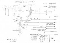
Attached is a schmatic drawing of 71A/6DJ8 sound processor.
Attachments
Interesting the 71 !
Attached is a schmatic drawing of 71A/6DJ8 sound processor.
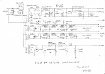
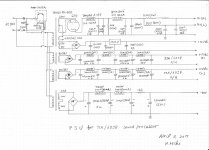
PSU for 71A/6DJ8 sound processor.
Attachments
H.Michi:
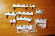
Where did you pick up the white terminal strips? ie the ones in your photo above of the bottom of you power supply? Do they screw mount to the chassis?
Where did you pick up the white terminal strips? ie the ones in your photo above of the bottom of you power supply? Do they screw mount to the chassis?
Those terminal strips look a lot like the ones I have so diligently removed from many a Tek scope for my projects. 😱 Worth the effort😉
H.Michi:
Where did you pick up the white terminal strips? ie the ones in your photo above of the bottom of you power supply? Do they screw mount to the chassis?
I bought thease terminal strips at a shop in Akihabara, Tokyo and some of them via internet. Yes, they are fixed to the chassis by screws. They are three kinds; 2mm,2.5mm and 3mm. Thease terminal strips were originally used in professional comunication or measurement equipments. some of recent products are not so good in quality and pron to separate metal part from ceramic body.
Attachments
Updated status of the 71A/6DJ8 sound processor
By increasing plate voltage and its current of 71A. I could see wider in dynamic range and more in clarity. For further touch-up, this time I put emphasis on my ear through listening rather than via measuring instruments. For references, I tried routin measurements and found that the output voltage was lower than the input one! I would say it is an active attenuator. However, it is not an issue for me as my main amps can generate maximum output power by 0.4 to 0.6V input and the setting position of main volume is around 11:00 to 12:00 O'clock. The residual noise level was 0.004mV which was far lower to what I assumed. It is attributed to the massive incorporation of passive LC filters and provided independent power transformers to those: HT, filament and bias circuit respectively.
Results measured at 1KHz, 600 ohm load
Output voltage, distortion , input voltage,
1.0V , 0.4% , 1.3V,
0.5V , 0.18% , 0.64V,
0.1V , 0.018% , 0.12V,
R-channel of 71A
Plate voltage: 134V
Plate current: 13.8mA
Grid bias: -25.8V
Attachments
- Status
- Not open for further replies.