350 volts DC was the standard anode/plate voltage of the majority of 6V6G single-ended audio UK radio tubes/valves of the late 30,s, 40,s into the early 50,s and yes I still like that valve/tube.
Klimon,
You did ask the million-dollar question. Unfortunately I have the 10 cent answer.
Don't get too hung up on exact voltage
Around 330=>340V worked best for me (subjective opinion ONLY).
Thanks a million, Ian. That more than answers it for me.
Nice schematic!
Just a couple of observations:
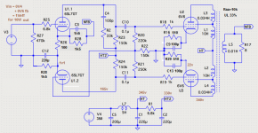
1. Change R28 to 1.4k; it gives equal self bias resistance for each section of the 6SL7GT.
2. Change R20 and R21 to be equal (either both 220k or both 250k); it balances the load from the output tubes grid circuits that the 6SL7GT driver plates see.
Just a couple of observations:
1. Change R28 to 1.4k; it gives equal self bias resistance for each section of the 6SL7GT.
2. Change R20 and R21 to be equal (either both 220k or both 250k); it balances the load from the output tubes grid circuits that the 6SL7GT driver plates see.
Mona, great to have your input. The output stage is exactly how I intend to rebuild it.
And I much appreciate your take on the phase splitter:
- I'll blindly copy the new cathode circuit.
- Are the slightly differing values of anode loads and resistor to ground (R22) worthwhile to implement? I could quite easily...
- And I'll add the C4&R2 loop.
I'm running the amp with the nfb switch off - bass sucks either way but instrument timbres and especially cymbals are a treat. Do you know how many db's nfb it has dialed in now?
@6a3: well spotted that R20/21 deviation. Typo? Will just leave the 270k I have now. For R28 I'll see what I have on hand.
Lastly: R25 is not a critical value, just a grid stopper, right?
Dank je wel!
Simon
Last edited:
I made a mistake, sorry.
I think now I see why R20 and R21 are unequal.
It is to give a small signal to the grid of U1.2.
With equal dividers, and at the same time equal driver plate signals, that is impossible.
Because with equal dividers, and equal out of phase plate signals, the output to U1.2 grid would be zero.
And Mona, very few mistakes ever gets past your critical eyes.
Last edited:
The different values for R20...R24 and C4&R2 are from Buffin tested in Spice.- Are the slightly differing values of anode loads and resistor to ground (R22) worthwhile to implement? I could quite easily...
With 1V in there is 0,6V to compensate for the feed back.I'm running the amp with the nfb switch off - bass sucks either way but instrument timbres and especially cymbals are a treat. Do you know how many db's nfb it has dialed in now?
To have no feed back, connect R28 to ground not to the speaker.
The two R28 (cathode resistors) are the same resulting in equal cathode voltages, no DC current trough R26.
R20 and R21 equal is only right if the gain of the triode is ∞ .The different values are to get a phase inverter with a gain minus 1.@6a3: well spotted that R20/21 deviation. Typo? Will just leave the 270k I have now. For R28 I'll see what I have on hand.
Yes.Lastly: R25 is not a critical value, just a grid stopper, right?
Mona
Change R28 to 1.4k; it gives equal self bias resistance for each section of the 6SL7GT.
There are two R28's in the schematic, both 1K5. But I don't see how lowering one of them would equal the self bias resistance.
"The different values for R20...R24 and C4&R2 are from Buffin tested in Spice"
Understood - I was looking at the original schematic 😉
Thanks for your clarifications, Mona.
All set to heat up the iron now
Understood - I was looking at the original schematic 😉
Thanks for your clarifications, Mona.
All set to heat up the iron now
Some last minute questions in the middle of surgery:
- R26 (between 6sl7 cathodes): can I use 47R instead of 100R?
- R22 (6sl7 grid to ground): is 120k okay instead of 150k?
And lastly the C4 & R2 loop isn't there. Worthwhile to add, or never mind?
TIA - nearly there
- R26 (between 6sl7 cathodes): can I use 47R instead of 100R?
- R22 (6sl7 grid to ground): is 120k okay instead of 150k?
And lastly the C4 & R2 loop isn't there. Worthwhile to add, or never mind?
TIA - nearly there
Never mind the two first questions, I found the prescribed resistors.
Still interested in advice on the C4/R2 loop though 😉
Also guess it's getting time to get a grasp on spice myself
Still interested in advice on the C4/R2 loop though 😉
Also guess it's getting time to get a grasp on spice myself
Well, I did it all at once & once and for all:
- mods to inverter circuit + separate output cathodes; no nfb
- upgraded all caps, resistors & went with toroidy output iron
I can only say that I didn't imagine this to be possible: what a delight 😱
Hats off to all of you marvel-making freaks... I hear ya 😉
Simon
- mods to inverter circuit + separate output cathodes; no nfb
- upgraded all caps, resistors & went with toroidy output iron
I can only say that I didn't imagine this to be possible: what a delight 😱
Hats off to all of you marvel-making freaks... I hear ya 😉
Simon
 So, you have it up and running now? Congratulations. 👏
Just to be clear, which schematic did you follow after all the discussion.
Thanks! Leap of faith working on that tiny pcb & inside the box...
Schematic in #23 = Mona's take on Dynaco 6v6 Push-Pull tube amplifier – Boffin's blog
No C3, C4, R2 + I added 230R UL screen resistors. Power supply 50uF-5H-175uF-2x30uF to inverter, all Clarity TC. Jensen pio coupling, Kaisei bipolar on cathodes. Blah (r).
It's a different amp, and it delivers 🙂
Schematic in #23 = Mona's take on Dynaco 6v6 Push-Pull tube amplifier – Boffin's blog
No C3, C4, R2 + I added 230R UL screen resistors. Power supply 50uF-5H-175uF-2x30uF to inverter, all Clarity TC. Jensen pio coupling, Kaisei bipolar on cathodes. Blah (r).
It's a different amp, and it delivers 🙂
Klimon,
Good job!
Have fun listening.
You are right about separate output tube cathode circuits:
Mona's schematic on Post #23 is very good.
The Boffin's blog schematic on Post # 34 is not as good.
For others who may wish to duplicate your amplifier, I describe what is often a major oversight on push pull amplifier circuits:
Unless you want to find Extremely well matched 6V6 pairs, the Individual Self Bias of Mona's schematic is required. The DC balance is quite good with fairly matched 6V6 pairs, and perfectly balanced for closely matched 6V6 pairs.
Using a common self bias resistor, and single bypass cap, is not a good idea.
Find the $ and the room for 1 more resistor, and 1 more bypass cap.
That way, the output transformer will be happy with new tubes, and will be happy years later when both tubes have aged.
Make sure to use 1% resistors, or better.
We are talking about a few 100s of microamps un-balanced plate currents;
versus several mA of un-balanced plate currents.
Last edited:
Hi Summer,
I did install separate cathode circuits, measuring spot on with matched quad.
On the splitter anodes there's quite some imbalance though on one channel (100 and 200 volts / the other 165 both sides): dumbstruck to achieve such a sound nonetheless. Probably unbalanced halves of the 6sl7s that came with the amp and which I never measured. Last thing to address, but an easy fix from where I'm coming.
Simon
Last edited:
Looked little closer at the Boffin amp.
Mona
Mona,
After Klimon’s successful build and launch I was looking closely at your take on the schematic and noticed that in the output transformer shows L1=10H and L3=0.034H. I don’t understand this for UL33% - could you help? Is it merely a typo or am I misunderstanding something?
Last edited:
Gnfb after all?
Sounding great, but a little too prominent highs (especially on lesser recordings). Will try the feedback loop in Mona's schematic from #23.
Curious to know how many db's it is: "With 1V in there is 0,6V to compensate for the feedback", but I'm lost in translation...
Cheers,
Simon
Sounding great, but a little too prominent highs (especially on lesser recordings). Will try the feedback loop in Mona's schematic from #23.
Curious to know how many db's it is: "With 1V in there is 0,6V to compensate for the feedback", but I'm lost in translation...
Cheers,
Simon
Those values for the OPT where there in the original schematic, like that it's allmost triode strapped.I didn't bother, makes no difference for the amp, only output power.Mona,
After Klimon’s successful build and launch I was looking closely at your take on the schematic and noticed that in the output transformer shows L1=10H and L3=0.034H. I don’t understand this for UL33% - could you help? Is it merely a typo or am I misunderstanding something?
Probably Simon used a "normal" transformer with 33 or 40% tap.
Mona
The input voltage is 0,4V. If you feed 0,6V back the total input becomes 0,4+0,6=1VSounding great, but a little too prominent highs (especially on lesser recordings). Will try the feedback loop in Mona's schematic from #23.
Curious to know how many db's it is: "With 1V in there is 0,6V to compensate for the feedback", but I'm lost in translation...
(If you feed 1V back the input needed becomes 1,4V.)
From 0,4 to 1 is x 2,5 and 20log2,5= ~8dB
Mona
- Home
- Amplifiers
- Tubes / Valves
- 6v6 PP UL bias point