Hello,
After some solid state-years I just rediscovered the magic of tubes 😉
Here's my cheap re-entry, bought 2nd hand: Dynaco 6v6 Push-Pull tube amplifier – Boffin's blog
Time to tinker...
First off, I could really use some pointers for a good bias point. The schematic is in the link, but the measured voltages are much higher: 330V cathode/anode 6v6, 20v bias, 40mA/tube. Seems quite hot.
Any recommendations, keeping the cathode bias and UL arrangement? It sounds good already, but I'll dig up some better caps and tubes as well as rebuilding the PS. Running fine without nfb.
Thanks,
Simon
40ma in push/pull for your plate voltage isn't far off the correct manufacturers data and 45ma in single ended configuration is standard (285V ) .
Many UK tube radios in the 40,s and even late 30,s had 6V6G tubes ---they always ran hot and I found that out when I was young with sore fingers.
I actually found it a pretty reliable tube although the ones I repaired had very low emission due to 24/7 use in radio ( gaga ) heyday.
Many UK tube radios in the 40,s and even late 30,s had 6V6G tubes ---they always ran hot and I found that out when I was young with sore fingers.
I actually found it a pretty reliable tube although the ones I repaired had very low emission due to 24/7 use in radio ( gaga ) heyday.
Thanks for the thumbs up, duncan and pcl200. I'm reassured: the pearl-scan shows the ancestor of my Chinese reissue with 340 volts on the plates / 22 v bias.
Wouldn't want to squander those grey glass RCA's hiding on my attic. They sounded lovely in SE... Now running philips ecg; I'm guessing there's room for improvement.
Wouldn't want to squander those grey glass RCA's hiding on my attic. They sounded lovely in SE... Now running philips ecg; I'm guessing there's room for improvement.
How about insuring that the 6V6 currents are close to each other.
Use individual self bias.
500 Ohm for each cathode, and 47uF to bypass each cathode.
You can always check the voltage across the 500 Ohm resistors, when the tubes are first put in, and later as they age.
And, your output transformers will love it. The better the current balance, the less chance you have of early core saturation.
Use individual self bias.
That's a good suggestion, but wouldn't I need 2x 100uF then?
Also wondering about nfb: it's switchable and sounds much better without (texture, soundstage), although a little harsh. I'll first try the cap/tube upgrades to see if it smoothens out. If not, thinking about adding ~300ohm screen resistors or a little fb (3-6db).
@Artosalo: nice definition, but unfortunately I have no means to measure thd.
This article does extensive testing of 6V6 SE UL showing optimum bias points at a range of B+ voltages.
Optimization of the 6V6 SE-UL | Cascade Tubes
Steve
Optimization of the 6V6 SE-UL | Cascade Tubes
Steve
That's quite a treasure for SE
Will just add a small value R under each cathode to keep track of imbalances, and keep the shared cathode R with bypass (the caps are already on their way...)
Will just add a small value R under each cathode to keep track of imbalances, and keep the shared cathode R with bypass (the caps are already on their way...)
That's a good suggestion, but wouldn't I need 2x 100uF then?
Not really. When you use a 500 ohm resistor in each cathode, each with its own 47 uf capacitor, you are already doubling the time constant for the RC combination, which halves the 3 dB corner frequency. You can increase the capacitor value to 100 uF if you want, though. That's not likely to cause any problems,
Ray Waters,
You are correct.
I forgot that this amp has global negative feedback.
So when modifying for individual bypass caps, it should benefit from having 100uF bypass capacitors.
In the case of the original shared self bias resistor and shared bypass capacitor, the cathode currents changed in opposite phases, which tended to cancel the currents when in class A, and the original bypass cap only had much action during the AB portion of the signal.
The change to individual self bias is well worth the effort.
Some amplifiers are accused of not sounding good because of a simple problem . . .
The DC current in the output transformer primary halves are un-balanced.
Last edited:
@Artosalo: nice definition, but unfortunately I have no means to measure thd.
Are you sure ? Only basic laptop pc is required and some freeware audio analyzer software.
"some freeware audio analyzer software"
I can look into that - what would you recommend?
Cheers!
I can look into that - what would you recommend?
Cheers!
I am not well aware about new versions, but this looks versatile:
fft analyzer software free download | FFT Spectrum Analyzer Freeware
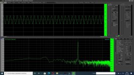
Attached a sample how 1 kHz tone from HP8903B's generator shows.
fft analyzer software free download | FFT Spectrum Analyzer Freeware
Attached a sample how 1 kHz tone from HP8903B's generator shows.
Attachments
Last edited:
I forgot that this amp has global negative feedback.
So when modifying for individual bypass caps, it should benefit from having 100uF bypass capacitors.
The change to individual self bias is well worth the effort.
I'll go the separate resistor route.

@Artosalo: thanks for the tip
See the Retrovox link at post #16 by 45 here
UL / Distributed Load - Screen vs. CFB Winding Ratios
Cheers,
Ian
UL / Distributed Load - Screen vs. CFB Winding Ratios
Cheers,
Ian
Thanks for that, Ian. The lower voltage coincides with what I found here: ultra-linear
And seems akin to what you use in your 6v6 baby huey (although fixed bias).
Since power is about the same for 300 and 350v, and tube-life would be prolonged, here's the million-dollar question: does it sound better?
Cheers
Simon
And seems akin to what you use in your 6v6 baby huey (although fixed bias).
Since power is about the same for 300 and 350v, and tube-life would be prolonged, here's the million-dollar question: does it sound better?
Cheers
Simon
Klimon,
You did ask the million-dollar question. Unfortunately I have the 10 cent answer.
6V6 is one of my favourite tubes and I have run them in triode/ultralinear/pentode mode at Vak voltages between 270 and 380V (for both guitar amps and HiFi Amps).
Around 330=>340V worked best for me (subjective opinion ONLY).
You need to be aware that the mains voltage fluctuates. Here in Oz we have 250V AC 50 Hz with a claimed 5% tolerance, on a 40+ degrees C day (105 F) when everyone in the street has their aircon cranked I've seen voltage dip below that -5% point, so when we say a Va of 340V we actually mean a Va of 323 to 357 Volts so don't get too hung up on exact voltage.
Ideally I would aim for 320V but am not fussed about +/- 30V.
Tubes are at best a +/- 10% device anyway.
I don't normally like poo poo'ing folk, but you should be aware that the link you posted above is to the site of an enthusiastic ameture and his views require review to separate fact from unsupported opinion. There are certainly opinions expressed which I would not (as a retired electronic design engineer and tube theory specialist) support. There is some valuable stuff there but also some stuff I would seriously disagree with, and some stuff which is conjecture at best on which (in the absence of evidence) I do not offer an opinion.
Cheers,
Ian
Last edited:
For additional info:
I use NOS Sydney AWV Factory 6V6G (the old ST :Coke Bottle" shape tubes) for both HiFi and Guitar.
I sometimes (2nd choice) use NOS RCA and similar 6V6GT for Guitar
AND I also use these (which are seriously good for guitar):
2 x 6V6GT / 6n6c REFLEKTOR RUSSIAN MILITARY TUBE * NOS NIB * MATCHED PAIR * | eBay
which in my Guitar Amp gave the "Creamiest" sound of any of the tube selections, to suit Folk, Blues and Classic Rock (but NOT shreader Metal Lead).
A local guitar god who plays in a Lead Zepelin tribute band, loved these in Ultarlinear with no global feedback. (with this 23% UL 10K Raa OT).
86PP output transformer
Last edited:
- Home
- Amplifiers
- Tubes / Valves
- 6v6 PP UL bias point