Using AC coupling to the scope for all captures I guess. Looking early rounding in the HF. Showing the same for the grounded grid pre maybe shows a trend in the measurement loop. What is the wave generator spec? What is the probe spec and its setting?
Scope is set on AC for the measures. Does that matter since its after the output cap?
Its this Very-High-Resolution Oscilloscopes from Pico Technnology one and the built in signal generator. I havent used it much so mebbe i have some settings wrong.
Probes... well, the ones that came with. It says 60 mHz on them. Setting x1
Staffan
Its this Very-High-Resolution Oscilloscopes from Pico Technnology one and the built in signal generator. I havent used it much so mebbe i have some settings wrong.
Probes... well, the ones that came with. It says 60 mHz on them. Setting x1
Staffan
Last edited:
Oscilloscope — Vertical
Bandwidth
±20 mV range
±10 mV range 5 MHz
4 MHz
3 MHz
Bandwidth limiter 200 kHz, switchable
Rise time (calculated)
±20 mV range
±10 mV range 70 ns
88 ns
117 ns
Signal Generator
Standard output signals Sine, square, triangle, DC voltage, ramp, sinc, Gaussian, half–sine, white noise, PRBS
Standard signal frequency DC to 20 kHz
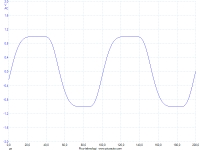
That last spec above means you should expect decent square up to 2kHz and its best rise time up to 1kHz only. Difficult to see wee HF wiggle if any is there with those rise times and bandwidths mentioned. But a low frequency one at 1kHz or under it should have been visible. AC coupling to a scope introduces further high pass but its not of interest here, avoid DC coupling in non HV CAT I capable mini scope interfaces inputs when probing valve gear. When a probe is set at X1 it drastically cuts its bandwidth spec to few MHZ but the system gains SNR is what happens. Still at much faster spec than the included generator, so its OK for that.
Bandwidth
±20 mV range
±10 mV range 5 MHz
4 MHz
3 MHz
Bandwidth limiter 200 kHz, switchable
Rise time (calculated)
±20 mV range
±10 mV range 70 ns
88 ns
117 ns
Signal Generator
Standard output signals Sine, square, triangle, DC voltage, ramp, sinc, Gaussian, half–sine, white noise, PRBS
Standard signal frequency DC to 20 kHz
That last spec above means you should expect decent square up to 2kHz and its best rise time up to 1kHz only. Difficult to see wee HF wiggle if any is there with those rise times and bandwidths mentioned. But a low frequency one at 1kHz or under it should have been visible. AC coupling to a scope introduces further high pass but its not of interest here, avoid DC coupling in non HV CAT I capable mini scope interfaces inputs when probing valve gear. When a probe is set at X1 it drastically cuts its bandwidth spec to few MHZ but the system gains SNR is what happens. Still at much faster spec than the included generator, so its OK for that.
I have a better (I think) signal generator somewhere that I might try tonight after i putted kiddo to bed. So I shall keep the other measurement settings?
I have a better (I think) signal generator somewhere that I might try tonight after i putted kiddo to bed. So I shall keep the other measurement settings?
If its cheap DDS it will have wiggles of its own on square waves. See if it can output 10-20kHz good squares as a loop to the scope first. Optimize any settings needed. If it can, then introduce the devices under test in the loop.
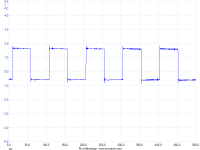
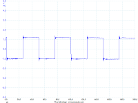
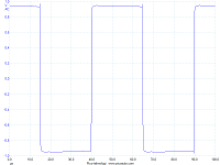
And heres an old Wavetek model 182 that can do the squares but with some nice wiggles
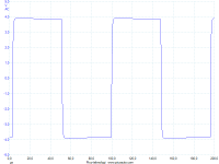
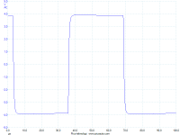
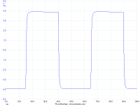
The Wavetek 182 is a vintage analog function generator. If its not faulty then the ripples are just the scope's A to D. Maybe that is why it sports such a heavily filtered 20kHz only integral gen and a 200kHz input bandwidth limit option. Introduce the limit and see if the ripples tame. That bandwidth will be enough for a 10kHz square and somewhat worse 20kHz square. In any case save what is best the combo can do in files for 1kHz-10kHz-20kHz and then compare when the DUT is in the loop. So to know what is inherent and what is not.
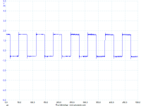
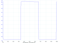
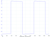
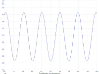
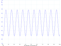
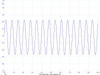
Heres the GG with Wavetek, 10kHz, 15kHz and 20kHz (same as above):
Posted when I was writing, so the bandwidth limitation of the DUT cuts on the ripples of when the gen is introduced directly to the Pico Scope without its BW limit function engaged. Looks ripple free now.
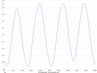
Looks like passing all the audio range fast and clean since it can do nice squares up to 20kHz. See about its frequency response is flat with sine waves amplitude in a good spread of frequencies too.
Well. Since I'm a total screwup on measurement I got a real surprice today when I came home and started to measure VRMS over freq spectra. I started with the Picos internal generator and with volume pot on somewhere half it ended up where it ended up. 526 mV on 1 k from 1 volt input. Measures were made on the Pico, it has a VRMS function.
I started plotting the values and to me it looks very linear response, under 1% deviation within the audible spectra.
I I began to think something must be wrong so I loaded grandpa Wavetek. I calibrated to 526 mV at 1kHz and started from 10Hz. Wopsie, granpa still works. It might deviate on a mV somewhere (can be tempdrifts, the xformer gets hot). So I ran it up to granpas max 2Mhz and both the DUT and Pico is answering up.
Please tell me I'm doing something wrong.
Heres a link to the excel chart https://skydrive.live.com/?cid=a82ae51e025d3d97#cid=A82AE51E025D3D97&id=A82AE51E025D3D97!2910
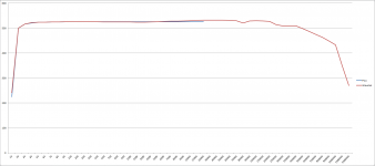
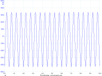
Chart, 500kHz, 1MHz, 1,5 MHz and 2 mHz
I started plotting the values and to me it looks very linear response, under 1% deviation within the audible spectra.
I I began to think something must be wrong so I loaded grandpa Wavetek. I calibrated to 526 mV at 1kHz and started from 10Hz. Wopsie, granpa still works. It might deviate on a mV somewhere (can be tempdrifts, the xformer gets hot). So I ran it up to granpas max 2Mhz and both the DUT and Pico is answering up.
Please tell me I'm doing something wrong.
Heres a link to the excel chart https://skydrive.live.com/?cid=a82ae51e025d3d97#cid=A82AE51E025D3D97&id=A82AE51E025D3D97!2910
Chart, 500kHz, 1MHz, 1,5 MHz and 2 mHz
Attachments
Last edited:
Don't be surprised, in buffer mode it really goes much high. The small dips should be just the generator's calibration response. (350mV is 1.5MHz -3dB in your chart).
- Home
- Amplifiers
- Tubes / Valves
- 6V6 line preamp