Comprehensive Schematic.
Hello,
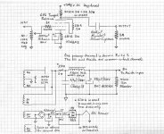
Some people emailed me asking for a comprehensive schematic of how I made it, with final PSU etc. So here it is. Although it is explained in the thread, its better to be in one picture.

The Mosfet Maida style regulator used can be seen here. I made it point to point on perfboard though. You must calculate its resistor divider voltage setter for 340-350VDC. Details on how, are in the given link.
*The 15R became 20R 2W after new tubes got run in and draw less for 6V+ heater voltage.
Hello,
Some people emailed me asking for a comprehensive schematic of how I made it, with final PSU etc. So here it is. Although it is explained in the thread, its better to be in one picture.
The Mosfet Maida style regulator used can be seen here. I made it point to point on perfboard though. You must calculate its resistor divider voltage setter for 340-350VDC. Details on how, are in the given link.
*The 15R became 20R 2W after new tubes got run in and draw less for 6V+ heater voltage.
Attachments

I saved a copy of this schematic. If I determine that my current 6EM7/crossover project needs more power I can rewire as a preamp similar to this and build a bigger power amp. The 6EM7 has a pretty low rp so it should do nicely in this type of layout me thinks.
It will need recalculation for DC PSU, operating point, resistors & heater current source amperage, for 6EM7 2nd section. You can keep the main idea, but as is, the circuit values are not applicable.
Yes, I should have mentioned that only the basic topology could be used since it is not only a different tube but an entirely different class (triode).
The cool thing with the 6V6 when triode wired as in this preamp, is that it approaches DHT linearity.😉
Appologies for going "slightly" OT.
Has anyone had experience with the circuit shown by foboleyns above. This is a triode mode variation.
Using the screen as an "anode" and AC grounding the real anode is something I've seen done with 6AU6 but not with higher power pentodes.
The theory is that the AC Grounded Anode completely surrounds the other tube elements and so should give some improved noise performance.
Can we expect any other improvements, that is, in linearity etc.
Thanks,
Ian
Hi Ian,
I have in mind to do that experiment on first opportunity, as I have seen it in some underground Japanese, but the thing that puts me off a bit, is that we create a much wimpier tube in that way. I want strong current in this preamp for example. Plus we should expect a different set of load lines.
I will repeat Ian's question then. Has anybody reviewed that topology?
foboleyns said:yes,The plate is run at a very low voltage, almost turning it off in this case,it make the 6V6 look like be close to a triode with low internal resistance.
A=5.5V is necessary,we can use a regulate circuit to make it adjustable for the output gain.
Interesting circuit. How much is gain, output impedance and harmonic distortion?
salas said:I want strong current in this preamp for example.
Why? I wonder what you are driving with this preamp, since with that 0.68 uF output cap, it must be high impedance.
Exactly so. Even with a 100K circuit as the load, I found a 1µF output coupling cap to open up the bottom and stage beyond what I would have thought. With a fractional µF cap on the output, we ain't gonna be delivering any big current to anything, no matter what.
On my commercial circuit, I use 2.2µF, simply because it will deliver true bottom into a 20K, or maybe even a little heavier load.
For stuff like current delivery and component values, we got to look at this stuff reasonably.
Aloha,
Poinz
On my commercial circuit, I use 2.2µF, simply because it will deliver true bottom into a 20K, or maybe even a little heavier load.
For stuff like current delivery and component values, we got to look at this stuff reasonably.
Aloha,
Poinz
I don't need it to deliver elevated current to the certain load. I had tested the certain setup with as high as 33uF film cap, as a coupler. The 0.68uF Mundorf delivered better subjective slam and stage on my 120k load. It sounds clearly more forceful in LF head to head with my DC coupled version of N-JFET PASS B1 buffer for instance.
It plays much better across the spectrum when biased strong. That's all. Goes without saying that the output capacitor in my schematic is just indicative for value or quality depending on load and taste.
It plays much better across the spectrum when biased strong. That's all. Goes without saying that the output capacitor in my schematic is just indicative for value or quality depending on load and taste.
Poindexter said:Exactly so. Even with a 100K circuit as the load, I found a 1µF output coupling cap to open up the bottom and stage beyond what I would have thought. With a fractional µF cap on the output, we ain't gonna be delivering any big current to anything, no matter what.
On my commercial circuit, I use 2.2µF, simply because it will deliver true bottom into a 20K, or maybe even a little heavier load.
For stuff like current delivery and component values, we got to look at this stuff reasonably.
Aloha,
Poinz
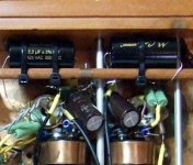
Guys, you put the bug in me and I got 2.2uF Mundorf Supreme to listen to. I put the biggish caps in and listened a lot. With my amplifier load there was no missing bass that I got back quantity wise. I just got a feeling of better coherence and a bit of more relaxation. Could be the phase turning much lower and preserving a better impulse response. Non the less I can hook up the odd solid state power amp with 20k or 10k input Z now with no bass loss.
Attachments
Have done so in other preamps, I don'tlike the effect subjectively in linear enough simple circuits.
These preamps could be of very high class...
rounded plate is better sonicaly,
other tubes have the simillar are 6F6, 300B etc.
*
the tip to improve for the maximum performance IS
topology with output transformer
because the present state is shifting phase for 180deg.
that one like JANE member post before...
*
go to the maximum G2 voltage
not Vbattery...
current of 75% of max at that point.
even with 50% of Io it will be in class A.
*
OT with at least 18Hy that is app. I can calculate better value...
anyway it is not demanding so.
with secondary CT for propper ballanced option...
*
the power supply should be separate for each channel,
as well as heating transformers,
it is vital that is not from the high voltage core
and for rectifiers too...
Experiment with the rectifiers for better sonic results
it is of merrit...
*
essential for fast sound, the load line,
decresing the value, in the same time watching the distorsion,
and keep it as low as possibile,
it could be extremly low like in a solid state,
because of low level signal,
and from the same reason Lp too...
this is much lower then present values...
in some cases of that preamp concepts,
they are close ti the internal resistance of the tube
lowering the equivalent output resistance rapidly...
*
remember You are not designing a power amp
with full swing input...
*
if You make this little effort You will be amazed...
*
microphony could be the problem, like it was stated before,
but that could be solved with soft connection of subchasees,
and changing the pairs and brands of tubes...
*
if I found, I will post the sch i was worked on in the past.
*
cheers
Salas You did the good job indeed
Zoran said:These preamps could be of very high class...
rounded plate is better sonicaly,
other tubes have the simillar are 6F6, 300B etc.
*
the tip to improve for the maximum performance IS
topology with output transformer
because the present state is shifting phase for 180deg.
that one like JANE member post before...
*
cheers
Salas You did the good job indeed
*Yes it is top class indeed. Have compared to many.
*I reverse at the speaker end. This one plays better than a 6C45PI with amorphous OPT of a friend. Used double mono regulators, no difference than with a common reg. Uses separate current sources for heaters, has 2 separate windings. Don't know for different heater trafo benefit as in AC heating.
*Thank you for your nice comment.
Hi all ! IMHO , 6V6 is great in PP config, 6F6 far better in SE ... look at the 348/349A (6C6/42 , 6J7/6F6) Western line amp ... my next DIYproject 😉
The comparsion of the tube preamps,
is dificult...
Because there is very few from right techical topology...
*
they could be charakterised like fashion:
over-aplifiing signal...
oposite phase devices...
easy to build and repeted wrong design...
or they are just cathode follower buffers...
*
something is always wrong,
once that is the value of pot,
second is value of Rk, Ck is constant example too...
load values, power supply, heating, ...
etc
*
while the topologyes remains the same,
tube types changing, trying to make the difference.
*
SO WHY NOT DESIGN A DEVICE FOR OTHER TO COMPARE WITH?
''Hi all ! IMHO , 6V6 is great in PP config, 6F6 far better in SE ... look at the 348/349A (6C6/42 , 6J7/6F6) Western line amp ... my next DIYproject ''
Really good, but will require OPT. No better than 2.7k output Z in triode. And adding OPT is to make or break. Very crucial addition.
Really good, but will require OPT. No better than 2.7k output Z in triode. And adding OPT is to make or break. Very crucial addition.
Zoran said:The comparsion of the tube preamps,
is dificult...
Because there is very few from right techical topology...
*
they could be charakterised like fashion:
over-aplifiing signal...
oposite phase devices...
easy to build and repeted wrong design...
or they are just cathode follower buffers...
*
something is always wrong,
once that is the value of pot,
second is value of Rk, Ck is constant example too...
load values, power supply, heating, ...
etc
*
while the topologyes remains the same,
tube types changing, trying to make the difference.
*
SO WHY NOT DESIGN A DEVICE FOR OTHER TO COMPARE WITH?
Have had comparisons with circa $20k commercial tube preamp products that I performed service for. Considered reference by international audio press. Also about 7 diy tube line schematics including 12B4 single stage favored by many, and Allen Wright 5687 constant current & constant voltage mosfet controlled schematic. More or less I have a fair comparison idea. Its up there among top class. All else is fine tuning for taste or particular system synergy. Also to mention, that to the same conclusion ended up a friend who makes and compares whatever he sees interesting all the time. Has a full tube system. From 0.25mV to 20W, no hiss or buzz. He uses this 6V6 one for line duty in the end. If I ever feel like it, I may try OPT, or other tweaks. As it is is nice enough non the less.
Thanx for comments. Appreciated. I keep the info.
- Home
- Amplifiers
- Tubes / Valves
- 6V6 line preamp