Salas,
You said: "Single one is good, but dual mono always give wider soundstage if cost and space is no object."
True!
However, there is something about channel separation that it seems is often not considered:
I designed and build a single ended stereo 45 amplifier on a single chassis, single B+, single filament supply.
The channel separation from 20Hz to 20kHz was -40 dB. That is not what many hi fi designers call good.
But everybody at work liked the sound of my system, and nobody complained about the [lack of] separation.
I expect that channel separation that might be more of a problem, goes more like this . . .
Channel separation:
40Hz -20 dB
1kHz -55 dB
7kHz -25 dB
That separation is not constant versus frequency.
But the channel separation of the original performance in front of the stereo microphones was relatively constant from 20Hz to 20kHz.
It might be harder to fool our ears and brains that the instruments and singers frequencies did not all have the same separation or placement in the sound stage.
We might hear the "position" of a performer appear to shift, as they run up and down the scale for 1 to 2 octaves, is not natural to the original performance.
That, versus a less than ideal dB number, but that is constant separation all the way from 20Hz to 20kHz; so there is No position-shifting of the performer.

Lp playback systems sound Do very good.
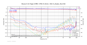
But sometimes the measurement results would make you wonder how.
Here is one measurement setup example of the channel separation and 2nd and 3rd harmonic distortion of a Shure V15 V phono cartridge.
Your favorite phono cartridge, and your best Test LP . . . may give similar or different results.
But sometimes the measurement results would make you wonder how.
Here is one measurement setup example of the channel separation and 2nd and 3rd harmonic distortion of a Shure V15 V phono cartridge.
Your favorite phono cartridge, and your best Test LP . . . may give similar or different results.
Attachments
Separate supplies per channel usually provide for less dynamic interaction between them on top of what separation there is already, so bit less dynamic image blurring. Not so in op-amp circuits which measure great PSRR, but in simple tube circuits they rather help.
A Playback System, is just that . . . a System.
Channel separation results depends on:
The recording
The playback (cartridge; CD player, etc).
The preamp
The power amp
The loudspeaker polar response; their relative position and angular rotation; and the room they are in.
Which ever part of the above has the worst separation, the rest of the components can not fix it, they can only keep from making it worse.
When I cook, I always peel the dry layer, and the next layer off of the onion.
Without doing that first, it is pointless for me to worry about the condition and flavor of the rest of the onion.
i did a 5X hybrid line amp using the 6N3P-EV - it measures well, though it depends on dreaded feedback to get its message across.
The circuit is shown below:

The circuit is shown below:
You are welcome. Happy that you like it. Which one version you implemented?Keeping this thread alive...
View attachment 1345149
I put this together last week and am very impressed.
Thanks to Salas and all who have contributed .
Yes, read the entire thread...
I will definitely tidy it up in a proper chassis.
Can you tell us a few words about its power supplies configuration and some info about the audio system this 6V6 preamp plays in?
Elevated DC heaters and a Maida regulator for the B+
The power supply is a 5U4GB, clclc to the regulator, maybe over kill on filtering but is darn sure quiet.
Driving 2a3 amps, I have diy SE and PP amps, Lenco TT diy tone arms, Hagerman Cornet hybrid, pi streamer via diy dac.
Speakers are WE clones, bass with 12" Jensen field coils, Horns are from Lycan R&R with Altec cd.
Dear All,
I read the entire thread and found many recommendations, but: could someone please post a highly recommended, concrete, must-build PSU circuit?
Many thanks in advance.
I read the entire thread and found many recommendations, but: could someone please post a highly recommended, concrete, must-build PSU circuit?
Many thanks in advance.

This is a cool all-DIY system with real scale speakers. Lots of careful work. Some essential room treatment there too. Congrats.Elevated DC heaters and a Maida regulator for the B+
The power supply is a 5U4GB, clclc to the regulator, maybe over kill on filtering but is darn sure quiet.
Driving 2a3 amps, I have diy SE and PP amps, Lenco TT diy tone arms, Hagerman Cornet hybrid, pi streamer via diy dac.
Speakers are WE clones, bass with 12" Jensen field coils, Horns are from Lycan R&R with Altec cd.

What you use for stabilizing DC on the 6V6 filaments? I saw a small board with a sink. Some low dropout MIC reg chip I would think.
Did you get the chance to evaluate how your G3X version 6V6 pre synergises in this system against some previous circuit you used?
Many thanks, Salas!Post#1 has a link to the SSHV2 shunt regulator's diagram and description
Wow, that is interesting! Would you mind explaining the circuit a little for those of us who fail to comprehend it?i did a 5X hybrid line amp using the 6N3P-EV - it measures well, though it depends on dreaded feedback to get its message across.
The circuit is shown below:
View attachment 1345276
I see V3 has a CCS on top (Q9).
But I'm not sure what Q5 is doing. Is that driving NFB to V3's cathode through R30?
What are R25 and C15 doing?
I guess R24 (bypassed by C15) lifts the volume control and V3 grid above ground. For what purpose?
I don't think I've seen anything quite like that before, and it's really interesting. Thanks.
Positive bias is applied to the input to help center the output voltage at around 30-50V to avoid clipping. The current source at the plate of the triode forces a constant current through the triode, so that any drive at the triode grid forces the p-channel mosfet to conduct and provide direct feedback via the triode cathode.
I've used this basic gain cell with both solid state and vacuum state devices - simulated THD (with solid state, I haven't gotten around to doing modelling for vacuum state devices yet) is very low(<0.001%) for such a simple circuit.
I've used this basic gain cell with both solid state and vacuum state devices - simulated THD (with solid state, I haven't gotten around to doing modelling for vacuum state devices yet) is very low(<0.001%) for such a simple circuit.
Nothing wrong with a little, properly implemented, feedback. Simple, elegant circuit!i did a 5X hybrid line amp using the 6N3P-EV - it measures well, though it depends on dreaded feedback to get its message across.
The circuit is shown below:
View attachment 1345276
Dan
- Home
- Amplifiers
- Tubes / Valves
- 6V6 line preamp