i think its my board MIC5156 based, 6.3VAC to 6.3VDCWhat you use for stabilizing DC on the 6V6 filaments? I saw a small board with a sink. Some low dropout MIC reg chip I would think.
Attachments

Thank youThis is a cool all-DIY system with real scale speakers. Lots of careful work. Some essential room treatment there too. Congrats.
What you use for stabilizing DC on the 6V6 filaments? I saw a small board with a sink. Some low dropout MIC reg chip I would think.
Did you get the chance to evaluate your G3X version 6V6 pre synergises in this system against some previous circuit you used?

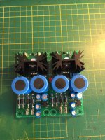
The DC heaters are boards from this thread
https://www.diyaudio.com/community/...pplies-mic5156-based-tube-amp-upgrade.382265/
I have a 12b4a preamp based on Eli's schematic in that thread, but it uses Al's gyrator.
They are both very good sounding and quite similar.
The 6v6 is a simpler build to get quite. I went through a few sets of 12b4a to get a quiet pair.
Nice DIY chassis. I like the color scheme. 12B4A with gyrator is no slouch. Bold and clear. Must be careful avoiding noises indeed due to its high gm. My old experiments and findings posts with the 12B4 and a gyrator I designed for it.Thank you
The DC heaters are boards from this thread
https://www.diyaudio.com/community/...pplies-mic5156-based-tube-amp-upgrade.382265/
I have a 12b4a preamp based on Eli's schematic in that thread, but it uses Al's gyrator.
They are both very good sounding and quite similar.
The 6v6 is a simpler build to get quite. I went through a few sets of 12b4a to get a quiet pair.
I found the 6V6 line preamp simpler as you say, also more tonally classic in my humble opinion. Due to the type's historic popularity many brands and equivalents to play with aswell. Very low Ra high gm tubes tended to sound bit more technical to me. By the way 5AR4/GZ34 rectifiers are also interesting to try in your G3X 6V6 if you got any.
The output Mosfet is just an NFB buffer stage or it significantly contributes to the OLG?In the final implementation of the 6N3P-EV line amp circuit, I ended up using an SOT-223 mosfet with a little lower gate capacitance than the IRF9610 used in the schematic shown. I utilized PCB heat sinking to keep the mosfet in the output stage cool.
It's a significant contributor to the OLG - with this gain cell. I used to reflexively put a cascode device between the input device and the current source load, fearing amplified Miller capacitance, but when I bothered to actually measure the voltage excursion at the drain/plate of the input device in simulation, I found that the gain there was significantly below 0dB, likely due to the stiff feedback from the output p-channel mosfet. The line amp has a closed loop gain of only 5X, so any gain there is is dumped right back to the summing node at the source/cathode of whatever input device I'm using. So, when I use this gain cell now, I have no worries about amplified Miller capacitance, as the input stage has a gain significantly less than one.
My motivation for transitioning to a surface mount-p-channel mosfet was lower gate capacitance (100 pF vs. 170pF), so zippier drive with the available current from the input stage.
My motivation for transitioning to a surface mount-p-channel mosfet was lower gate capacitance (100 pF vs. 170pF), so zippier drive with the available current from the input stage.
Last edited:
I popped that circuit into LTspice and I can't get it to draw current. Just the resistors draw current. The CCS does not, so the 6N3P doesn't either. Can I share the .asc file with you so you can check my work? (Still very interested in this circuit.)
It could be that I don't have the correct models for the MOSFETs. What would be equivalent to a BSS159?
It could be that I don't have the correct models for the MOSFETs. What would be equivalent to a BSS159?
Attachments
A BSS159 - it's a depletion mode mosfet, so it draws current with no gate drive. I use them all the time for current source loads, as they have low capacitance. I suppose you could try using something like a J112 n-channel jfet instead, if you have the model for it. It likely won't work quite as well as the BSS159, as it's a short-channel jfet used for switching applications. Fortunately, I have the BSS159 model in my PSpice library.
Last edited:
If you could share that BSS159 model, I might be able to convert it to an LTspice model.
I was using an LND150 model, but that's probably not even close to a BSS159.
I have a J112 model to try. I just want to get it working so I can see the voltages and currents, try to puzzle out what it's doing.
How about the IRF9610? Can an IRF9640 sub for that?
I was using an LND150 model, but that's probably not even close to a BSS159.
I have a J112 model to try. I just want to get it working so I can see the voltages and currents, try to puzzle out what it's doing.
How about the IRF9610? Can an IRF9640 sub for that?
No to the IRF9640 - too damn much gate capacitance. Also, I don't have any way of yanking the BSS159 model out of PSpice to give to you. Go ahead and try the J112 - set it up for 5mA drain current.
Last edited:
I guess nobody noticed my Post # 4963; a graph of a Shure V15 V phono cartridge.
I am sorry I did not give tabular results, it is not easy to conclude the results without an easy to read table.
Separation:
15dB @ 30Hz
17dB @ 50Hz
19dB @ 100Hz
25dB @ 200Hz
27dB @ 1kHz
27dB @ 2kHz
26dB @ 5kHz
25dB @ 10kHz
Distortion:
5% @ 30Hz
4% @ 50Hz
2% @ 100Hz
0.6% @ 5kHz
0.8% @ 10kHz
A vacuum tube amplifier posting on Tubes/Valves with specifications the same as that cartridge, might not be widely accepted or liked.
Last edited:
Better not to introduce further comparable level distortions in a signal chain because its not only a matter of harmonic distortion masking threshold, but they can also beat together creating extra intermodulation distortion.A vacuum tube amplifier posting on Tubes/Valves with specifications the same as that cartridge, might not be widely accepted or liked.
I did not save the link to the V15 V tests.
So the test record was not noted; no velocity level, and no acceleration level noted.
Intermodulation distortion:
If there is 2nd harmonic distortion, plus if there are 2 tones, there will also be Intermodulation distortion.
(only one tone . . . Nothing to Intermoduate).
Where | 'quantity' | = absolute value of 'quantity':
Two Tones, F1 and F2
2nd Order Intermodulation Distortion frequencies will be:
F1 + F2; and |F1 - F2|
Two Tones, F1 and F2
The 3rd Order Intermodulation Distortion frequencies will be:
|(2x F1) - F2|; and |(2 x F2) - F1|
That is pretty much standard fare for phono cartridges, amplifiers, and loudspeakers.
Note: Loudspeakers that are multi-range, have crossovers. Those crossovers will limit what frequencies, F1 and F2, can reach a particular driver.
A single tone to a single driver can not cause intermodulation distortion in that driver.
But one frequency tone from one driver, and a different frequency tone from another driver, can cause Intermodulation Distortion in your Ear.
Rules and Results.
Music is many simultaneous sinewaves. Nearest correlated bench test should be the multitone test.
A perfect square wave is a series of the fundamental sine wave, plus an infinite series of odd harmonic sine waves.
A perfect square wave, except for any number other than a 50% duty cycle, is the fundamental sine wave, plus an infinite series of odd harmonic sine waves, plus an infinite series of even harmonic sine waves.
If there is a high frequency roll off, the infinite series are truncated [early], but then so is the shape of the square wave truncated, or otherwise distorted.
Is anybody surprised?
Other than for electronic music, I do not consider either of the above square waves to be musical, or to sound musical.
No acoustic instrument I know of sounds like that.
A flute, a clarinet, a french horn, a single piano note, and many other instrument's 'single' note, etc., create multiple sine waves; and so does your favorite singer.
Last edited:
Sorry to go off-topic again, but... First, thank you Salas for getting that .asc to run for me. That was kind of you, and very much appreciated.
This circuit looks simple enough but I'm finding it a challenge to figure out how it works. Good learning experience for me.
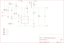
Now that I've looked at it a bit, it looks like the IRF9610, being a PMOS MOSFET, is the feedback loop. It amplifies in inverse polarity to the signal from the 6N3P plate. Correct?
Why is R3 (1M ohms) necessary in parallel with R1 (100k ohms)? Or is that to get 90.9k ohms exactly, and if so, why? Would a single 91k ohm resistor do just as well there? To me, it doesn't look like getting the precise bias voltage is that critical, but I'm not knowledgeable enough to say it is or it isn't.
Salas, please feel free to move this if you think it doesn't belong in this thread. I couldn't help myself.

Thanks.
Last edited:
You are welcome. Although I more or less read how it works, I will refrain from explaining this circuit because wrenchone is around who's its author. I hope he will answer your questions soon.
R22A R32A, R22B, and R32B are there because there is bias voltage present on the other side of each of the respective coupling capacitors. The resistors act to bleed down charge from the coupling capacitors so there is not a "pop" when the line amp is suddenly switched into the circuit. No nonsense about "magical" resistor values, just practical good sense.
- Home
- Amplifiers
- Tubes / Valves
- 6V6 line preamp