Would like to see a means to use this to build a LTP. Jumpers perhaps? I'd need 4 6V6's for a single linestage. Also no 'triode-ing' in the direct traces. 1 OZ copper traces that are a wee bit bigger than normal would also be of interest.
cheers,
Douglas
cheers,
Douglas
Guys hi,
Back in the thread I have been "petitioned" to offer an official PCB version for this long time popular preamp, mainly for the less point to point HV circuits expert members.
I was reluctant mainly due to excluding the variation possibilities when such a simple design gets fixed.
The 6V6 as a triode line preamp thread triggered many splendid sounding projects in fourteen years. It took on a life of its own in the best of DIY spirit.
It was even introduced to the kits world by a famous company. Don't know if directly inspired from this thread but its possible because existing long before. Isn't made like this one anyway. Has practical measures to work repeatedly in good noise spec that could be necessary compromises for product reliability and a price point in a gamut. Or not, I don't know.
So from all that I see there is sure interest for a defined form of the 6V6 line preamp and I endorse you guys to produce something for easier use in PCB. To widen access for more DIYA members to build and enjoy. You are free to decide the configuration. Don't ask me, you are super able makers.
Someday I owe to decide a set of practical factors and make a complete PCB version myself too. So to also give a signature design option in this thread honoring its success after so many years. Late is better than never.
Best of luck and health to us all.
Salas
Salas, this usage of mine is likely so specialized I'll be taking up a SE😛P design for myself. No sense saddling anybody else with my own needs. The last work, all done with p2p wiring was slightly troublesome...so will figuring out the PCB software. Oh well...LOL
I do like the phase splitter-less, balanced input amps though.
Douglas
I do like the phase splitter-less, balanced input amps though.
Douglas
That would be awesome!Someday I owe to decide a set of practical factors and make a complete PCB version myself too. So to also give a signature design option in this thread honoring its success after so many years. Late is better than never.
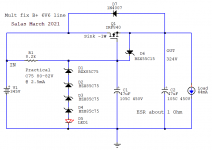
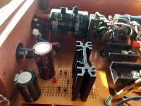
For the time being I would also like to contribute a simple capacitance multiplier alternative to the Maida B+ reg. The protoboard Mosfet Maida in the original build finally showed erratic reliability problems after many years of service. So I replaced it with this quick one to make and it worked well.
Hiss is as good as before. Ripple rejection few dB worse, but not audibly detrimental. In the cathode follower version at least. Sound is still very musical, maybe even more than before. Q1 Mosfet's dissipation is mild in this application, requiring just a small sink.
Enough builders opted for the much later introduced SSHV2 shunt reg than the initial Maida recommendation. Shunt is a whole different animal and effort. Too large for my original chassis.
Attachments
I use something similar to that PSU for several builds but with IRF820, works great!
So, simple gain stage version, big resistor ( with parallel pads for multiple resistors to spread the dissipation?)anode load, cathode resistor with optional bypass, and onboard output capacitors? Offboard PSU? First version will be octal, then maybe a noval and 6P1P or 6AQ5 varant? Once the main board is down it's easy to modify it for different sockets, and work on variations. I personally think a 6P43P-E version would be interesting for lower voltages 🙂
I don't use a ton of audio-shop specific parts so just need to know lead spacing on the types of parts y'all are likely to use, so I can give room to accommodate several sizes on the board. If you haave links to specific components that would even be better. Since we are just looking at two octal sockets a 100mm square PCB should be plenty of room I believe. Cheap and easy to have made at a place like JLCPCB.
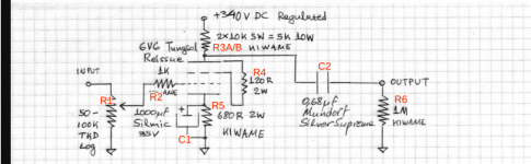
This is the schematic I will go off of from this post, and will design for the listed parts with a bit of leeway to fit alternative components. I think for the anode load 30-35mm lead spacing for parallel 5w resistors should accommodate most of the parts likely to be used, and for the other resistors I'll try to size for 1~2 watt or larger footprints to use kiwame and similar sized parts, as they are 12 or 24mm lead spacing.Cathode bypass cap assuming a 35 volt Elna Silmic will be 5mm lead spacing for radial footprint parts. Still not sure how best to fit footprints for output capacitors. A 1200 volt .68uF Mundorf is 21x41mm, so maybe 50mm lead spacing with some additional pads inline for smaller caps to also fit?
At this time I will focus on just the preamplifier signal circuitry, PSU will be offboard, unless you guys want the filament regulator to be included, assuming it will fit? As shown it's a CCS configuration, and Voltage regulator would also work well. I personally like all my power supplies on separate boards, so looking forward to hear what everyone wants to do. I'm likely to run AC heaters directly to the sockets personally, but I know lots of folks prefer DC in a preamplifier.
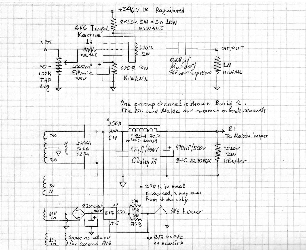
At this time I will focus on just the preamplifier signal circuitry, PSU will be offboard, unless you guys want the filament regulator to be included, assuming it will fit? As shown it's a CCS configuration, and Voltage regulator would also work well. I personally like all my power supplies on separate boards, so looking forward to hear what everyone wants to do. I'm likely to run AC heaters directly to the sockets personally, but I know lots of folks prefer DC in a preamplifier.
Last edited:
Awesome. I’m good with ac fili’s. Everything you’ve described is cool.This is the schematic I will go off of from this post, and will design for the listed parts with a bit of leeway to fit alternative components. I think for the anode load 30-35mm lead spacing for parallel 5w resistors should accommodate most of the parts likely to be used, and for the other resistors I'll try to size for 1~2 watt or larger footprints to use kiwame and similar sized parts, as they are 12 or 24mm lead spacing.Cathode bypass cap assuming a 35 volt Elna Silmic will be 5mm lead spacing for radial footprint parts. Still not sure how best to fit footprints for output capacitors. A 1200 volt .68uF Mundorf is 21x41mm, so maybe 50mm lead spacing with some additional pads inline for smaller caps to also fit?
At this time I will focus on just the preamplifier signal circuitry, PSU will be offboard, unless you guys want the filament regulator to be included, assuming it will fit? As shown it's a CCS configuration, and Voltage regulator would also work well. I personally like all my power supplies on separate boards, so looking forward to hear what everyone wants to do. I'm likely to run AC heaters directly to the sockets personally, but I know lots of folks prefer DC in a preamplifier.
I assume the tube sockets (and any heatsinks) be on the opposite side as the components? So that the board can hug the ceiling of a chassis with only the external components poking out. Maybe some cooling holes under the hot resistors would be a good idea too. I think wiring a twisted pair directly to the filaments pads is a good idea, to not have a long filament track running across the board spreading its ugly hum around.
Last edited:
Yeah sockets on top, all other component outlines will be placed on the bottom, but it'll be plated through-hole of course, so you can place them on either side really. Holes underneath resistors will be no problem for air circulation. 🙂
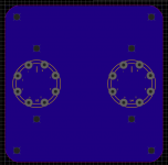
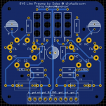
Initial layout of sockets, 4mm mounting holes, it'll have a ground plane with large clearances between traces and copper pour. Nice wide traces is the plan. I went ahead and put corner mounting holes as well as one on either side of the sockets. Does 4mm sound like enough? I think I usually see M3 holes on most other gear.
I figure a resistor between plate and screen will be a good idea, so maybe that works? I'll do the initial layout based off of the schematic posted by Salas, and then I'll add extra pads here and there as could be useful. I like PCBs with extra pads for experimenting anyway. You could even use this PCB for an SE output stage if you wired a transformer in instead of the load resistors 🙂
Would like to see a means to use this to build a LTP. Jumpers perhaps? I'd need 4 6V6's for a single linestage. Also no 'triode-ing' in the direct traces. 1 OZ copper traces that are a wee bit bigger than normal would also be of interest.
cheers,
Douglas
I figure a resistor between plate and screen will be a good idea, so maybe that works? I'll do the initial layout based off of the schematic posted by Salas, and then I'll add extra pads here and there as could be useful. I like PCBs with extra pads for experimenting anyway. You could even use this PCB for an SE output stage if you wired a transformer in instead of the load resistors 🙂
Attachments
Last edited:
I'm interested in a dedicated PCB also. That's a great idea and would be a real service to many of us that a lot of us would appreciate. I also vote for one pcb per channel. That gives more latitude for dimensional symmetry to put everything, including power supply in one box. For instance, I like putting preamp circuitry in front and and power supply in back. You could still use two boxes if you wanted to but a pcb per channel gives you more options if you wanted to put it in just one box.
Edit: You could also accommodate this idea with one preamp circuitry pcb for both channels and still keep it in one box. It would then need to be a somewhat long and narrow rectangle pcb. I just would NOT like it to be one square PCB for both channels because that precludes optimizing it for different housing arrangements for individuals different needs.
Edit: You could also accommodate this idea with one preamp circuitry pcb for both channels and still keep it in one box. It would then need to be a somewhat long and narrow rectangle pcb. I just would NOT like it to be one square PCB for both channels because that precludes optimizing it for different housing arrangements for individuals different needs.
Last edited:
Currently in progress on a stereo PCB with offboard PSU, after that is complete I can split it off into mono PCBs. A single board stereo PCB will be a bit better for less complex beginner type builds, and dual mono will work well for "power users" so to speak. Personally I think that mono PCBs with the filament regulator on each board per tube would be a nice option.
One thing at a time 🙂
One thing at a time 🙂
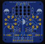
Current state of board, still scooting things around. I had to add my own labels for the parts, so as of right now all the left channel is R1, R2, C1, etc, and the right channel is R11, R12, C11 etc. I made the grid stoppers (R2, R22) smaller footprint so that they will be more effective using physically smaller parts right up to the socket pin. Capacitor footprint spacing will allow 10mm, 15mm box types, all the way up to 45mm spacing for larger "audio" type axial caps. I still have to add some holes near the filament pins.
Attachments
Last edited:
This is the schematic I'm using, with the added labels of the parts as they sit on the board. I added C3 as a power reservoir cap on the board, and I've replaced the volume pot with a fixed resistor on the board, which of course can be left off if desired- but I highly recommend running a resistor here, even with a pot. Make it 6-10 times larger.
Hopefully nobody has issue with either addition, as they will be useful for beginners and different configurations, and can be left off if not needed.
I also added the pads for filament wiring both under and next to the socket, so that multiple wiring configurations can be done, series, parallel, independent, etc.
All medium resistors are 16.5mm lead spacing, which will accommodate 1 and 2 watt kiwame or similar, and the anode resistors are 30mm lead spacing, to accommodate most 5w or larger resistors (and the listed kiwames) with holes underneath for airflow.
Attachments
Last edited:
- Home
- Amplifiers
- Tubes / Valves
- 6V6 line preamp