Aaaah those...I'll have a look thanks!Those two electrolytic caps near the TO-126
[edit]Indeed they bulge a little. Same as on my other board...strange...I'll have to keep an eye on those. (better still....replace them) They are rated for 400V. So nut sure why they are bulging.
Last edited:
 Will do. Well spotted! Thanks.
Nearing closer. I think I'm done actually, although I might have some questions in the coming days....Maybe later I rework the heaters to DC.
But listening the last few hours, I have to say this makes a very fine headphone amp for hiZ headphones. Sounds utterly fantastic. Not even a hint of hum, hiss or any noise of any kind to my ears. Really, it sounds wonderful.
Hooking up to an amp and speakers, in CF mode also sounds amazing. Big beautiful sound. No hiss. I can hear a bit of hum hear pressed up to speakers.
In gain mode though, I do hear a fair amount of noise going direct to amp and speakers. Some HF hiss, and quite a bit more hum. In addition to hum, there is a bit of very low volume pulsing. I really have to listen closely, but it's there. I'm making it sound worse than it is- still quite tolerable. Sounds, timbre, tone and everything still sounds excellent, it's just not totally quiet in gain mode. I might poke around in the coming days, but really this preamp and HP amp sounds really incredible across the board. Thank you Salas for your kind support of this thread for 14 years!
Nice work!
Salas,
I have both 5k-16 ohm and 5k-600 ohm OPTs to play with for an EL 84 / 6BQ5 line stage. It's supposed be really good. However, I realize posting this is a bit of a hijack since your audio circuit is just a buffer for El-84.
I have both 5k-16 ohm and 5k-600 ohm OPTs to play with for an EL 84 / 6BQ5 line stage. It's supposed be really good. However, I realize posting this is a bit of a hijack since your audio circuit is just a buffer for El-84.
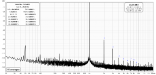
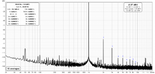
Attached are some measurements I made with a Quantasylum QA400.
For your reference, here are a couple of measurements I made on the follower version today. 2V RMS input ~1VRMS output (near 0dBV) for the volume pot to be at half division on its max output impedance and contribute all of its noise. Used an old music recording interface from E-MU on ASIO.
First chart is for 6Π6C Soviet NOS (Saratov factory Reflector logo also marked x 69 and OTK)
Second chart is for 6V6GT Tung-Sol currently made in the same factory for New Sensor corp.
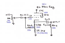
Heater PSUs are DC. Dual mono current sources set at ~0.45A each. From the original gain mode schematic*
*It can be found linked in post#1 as "comprehensive schematic".
Attachments
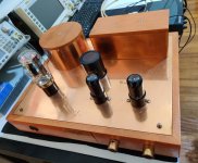
Thanks. Its the original chassis I designed back then. Time has taken its toll on the copper plates and turned knobs but it still holds.
Thanks for posting those measurements. I've actually got some parts to try out DC heaters so will post those in the next couple weeks.
From your experience what is the biggest contributor to H2? I've got consistently another 10db if it no matter which tubes I roll (-70db). I'm not overly concerned about it, mainly curious. Is it mostly about the output capacitor?
From your experience what is the biggest contributor to H2? I've got consistently another 10db if it no matter which tubes I roll (-70db). I'm not overly concerned about it, mainly curious. Is it mostly about the output capacitor?
It's because I have 10k//33k=7.7k instead of 5k main cathode load and 300V B+ in this example I would think. Bias current is 20mA. I did that at a point to can test lossier rectifier tubes and more rail drop on higher RC with the same power transformer. Although some may prefer the original H2 level.
Attachments
I see. Good to know! Regardless of which version, these are quite impressive numbers for a tube pre, and more importantly sounds outstanding too.
The 6p1p-ev is free from microphonics...at least the pair I had in my preamp. BUT here is the thing. I don't think this tube is on par with the 6v6 sound wise in a preamp. Last night I plugged it into my main system with and the sound was meh. It sounded fine in the my son's bedroom system though. (Not sure if the tubes were ok..I did not bother to try other 6p1p's I have in my stash)
Last edited:
So it seems to me. I remember the first 6v6 I built with the Tung Sol re-issue to sound great.
unregulated dc heaters
I decided to try a very basic unregulated DC heater just for giggles, cause I had some parts laying around. Seems to result in about 10db less noise in the 60/120/180 Hz points vs just AC. More details and some measurements later. But did I do this correctly? I blew the side door off one cap because I had the +/- reversed, but I'm hoping that was the only reason.
Specifically:
1) is it ok to use the center tap still tied to 80V? Resulted in less noise than when CT attached to 0V in this case.
2) Am I ok with 25V and 16V caps, even with it center tapped to 80V? I think so, since no current flowing there (I think).
I've got about 6.5VDC, but will try trimming it down just a bit more to 6.2 or thereabouts. The 6.3V winding is rated for 5A, so I should be ok even with the power factor loss.
Thanks!
Attachments

Raw DC has to have 120Hz ripple and smallish filter caps allow it more amplitude. You can see it on the scope. Choose AC coupling and probe across each one of the filter caps. Its pointy saw-tooth, mostly before any precious voltage eating RC damping, and if enough to couple well it can give a harsher harmonic noise profile.
Anyway, I would alternatively DC lift at the output i.e. at the heaters one side, to compare results. No danger to bias with a lifting DC in any single central node if the whole thing is floating. What matters to the filter caps rating is voltage difference across them not where they sit at in reference to some non correlated ground.
Anyway, I would alternatively DC lift at the output i.e. at the heaters one side, to compare results. No danger to bias with a lifting DC in any single central node if the whole thing is floating. What matters to the filter caps rating is voltage difference across them not where they sit at in reference to some non correlated ground.
- Home
- Amplifiers
- Tubes / Valves
- 6V6 line preamp