How do you calculate the bleeder resistor value? Is it just about corner frequency? For example in the original scehmeatic .68u/1M gives .2Hz.
Is the goal to shoot that low?
Is the goal to shoot that low?
Tom,
The resistor on the maida is 30R. For 4 tubes at 22ma + whatever loss in the regulator, is that enough headroom?
The resistor on the maida is 30R. For 4 tubes at 22ma + whatever loss in the regulator, is that enough headroom?
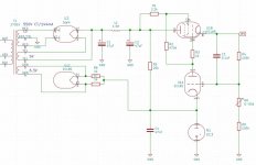
Well I'm well along fabricating my chassis for this exciting project, all the parts are kitted up, etc. I want to use a tube regulator. I believe others have used this old Gary Kaufman schematic with 0C3 reference and 6GV8 for the pass and error detector. I'll be using dual UF4007 diode bridges full dual mono regulators from a torroid with dual secondaries. Is this plan feasible for someone wanting to go "old school" instead of a modern maida regulator? I'll be using big MRC polypropylene in vegetable oil caps for all smoothing stages and decoupler, the only electrolytic will be the first reservoir at 450uf. Will I be ok you think?
Attachments
Bleeder Resistor value?
Do your mean a B+ Bleeder Resistor?
First, determine how long it takes from removing power to the amp, until you can unscrew and remove the bottom cover off the amp.
Example, 60 Seconds.
The total (parallel) Capacitance in the B+ filter, = C.
The Resistance of the Bleeder, = R.
R x C is one time constant.
The time for B+ to reduce to 37% of original voltage is 1 time constant.
In the second time constant, it will reduce to 37% of what was left after 1 time constant.
Let's use a 50k bleeder resistor, R.
Let's use a 300V B+, 200uF of total capacitance, C.
R x C: 200uF x 50k = 10 seconds
37% = 0.37
After 10 seconds, 300V x 37% = 111V
After 20 seconds, 111V x 37% = 41V.
The safety standard for some exposed test equipment probe tips, exposed terminals, etc. is 42 Volts (a knowledgeable electronic technician should still take some safety measures to not touch 42 Volts, or might get at least a small shock).
After 30 seconds, 41V x 0.37 = 15.2V.
If you take the bottom cover off quickly, you might not mind touching 15.2 Volts if you use dry hands, and if the bleeder resistor is well connected, and a high enough Wattage to keep from burning out at 300V.
Many 300V B+ power supplies rise to over 400V before the output tubes warm up.
300V/50k = 0.006A (6 mA).
300V x 0.006A = 1.8 Watts.
Use a 10 Watt Resistor (it will run cooler and is more reliable than using a 5 Watt resistor there). Or use two 25k 5 Watt resistors in series.
More capacitance C, then use less R Ohms.
More B+ Voltage, then use less R Ohms.
More power in the resistor, use a higher wattage rating.
Safety First!
Prevent the "Surviving Spouse Syndrome".
Last edited:
Put an LED in series with the resistor for a visual voltage present light. I use this as a power indicator.
1. If the LED fails, there goes the safety (once in a while LEDs do fail).
2. LEDs can operate over a large range of currents.
With a fixed bleeder resistor, that means they light up with full B+ voltage.
But they also will light up with B+ at 25% of normal voltage, but that can still bite your fingers.
2. LEDs can operate over a large range of currents.
With a fixed bleeder resistor, that means they light up with full B+ voltage.
But they also will light up with B+ at 25% of normal voltage, but that can still bite your fingers.
OK like in working alright? Green light there. The PSRR of this 6V6 circuit is lowish so anything obvious on the PSU rails will be noticed. The penthode pass element gives rather high output impedance compared to what is possible with solid state. Do not let this withhold you from trying as most SS regulators are not ideal either because they bring a certain sound with them. If you want something high spec look at the work of Jan Didden (among others).I want to use a tube regulator. I believe others have used this old Gary Kaufman schematic with 0C3 reference and 6GV8 for the pass and error detector. I'll be using dual UF4007 diode bridges full dual mono regulators from a toroid with dual secondaries. Is this plan feasible for someone wanting to go "old school" instead of a modern maida regulator? I'll be using big MRC polypropylene in vegetable oil caps for all smoothing stages and decoupler, the only electrolytic will be the first reservoir at 450uf. Will I be ok you think?
Last edited:
1. If the LED fails, there goes the safety (once in a while LEDs do fail).
2. LEDs can operate over a large range of currents.
With a fixed bleeder resistor, that means they light up with full B+ voltage.
But they also will light up with B+ at 25% of normal voltage, but that can still bite your fingers.
Resistors also fail. More often than LEDs in my experience. Still, you know if your power light is working or not...
🙂 I was right about this tube can be nice for a preamp too after all (2007)Bottlehead just released a 6V6 preamp kit.

Some more updates
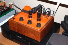
Nearing closer. I think I'm done actually, although I might have some questions in the coming days....Maybe later I rework the heaters to DC.
But listening the last few hours, I have to say this makes a very fine headphone amp for hiZ headphones. Sounds utterly fantastic. Not even a hint of hum, hiss or any noise of any kind to my ears. Really, it sounds wonderful.
Hooking up to an amp and speakers, in CF mode also sounds amazing. Big beautiful sound. No hiss. I can hear a bit of hum hear pressed up to speakers.
In gain mode though, I do hear a fair amount of noise going direct to amp and speakers. Some HF hiss, and quite a bit more hum. In addition to hum, there is a bit of very low volume pulsing. I really have to listen closely, but it's there. I'm making it sound worse than it is- still quite tolerable. Sounds, timbre, tone and everything still sounds excellent, it's just not totally quiet in gain mode. I might poke around in the coming days, but really this preamp and HP amp sounds really incredible across the board. Thank you Salas for your kind support of this thread for 14 years!
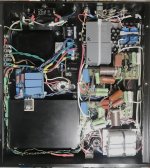
Attachments

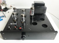
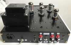
Looks like the night fighter version of 6V6 preamp builds. Very imposing. Congrats.
In gain mode handpicked low microphony tubes matter, elastic mounting also. Another way is to drop some non needed gain, first by not using the cathode bypass cap, or by going down even further with use of NFB schemes.
In gain mode handpicked low microphony tubes matter, elastic mounting also. Another way is to drop some non needed gain, first by not using the cathode bypass cap, or by going down even further with use of NFB schemes.
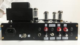
That is a good re-deployment of the Dyna Stereo 70's PA 060 Power Transformer.
Choke input B+?
Or . . . how did you get the B+ voltage lower than it is on the Stereo 70?
Choke input B+?
Or . . . how did you get the B+ voltage lower than it is on the Stereo 70?
Last edited:
I used Tom Christiansen's 21st century Maida regulator on his Neurochrome site.
Dialed in to 335V. Works a treat
Dialed in to 335V. Works a treat
That is a good re-deployment of the Dyna Stereo 70's PA 060 Power Transformer.
Choke input B+?
Or . . . how did you get the B+ voltage lower than it is on the Stereo 70?
You were right even before Bottlehead decided to use it. 😀I was right about this tube can be nice for a preamp too after all (2007)
- Home
- Amplifiers
- Tubes / Valves
- 6V6 line preamp