I would not worry too much about the chassis. I had my active crossover in an MDF box for years with no hum. Good layout will cure most of your problems I feel....
...
Cheers,
Chris
+1 to everything said here.
Many non-metalic chassis work fine.
I would also wire the 47K resistor on the other input grid of the 6SL7 directly to the pin. Same for the 1K resistors on the grids of the output tubes. This will help to stop some of the screaming.
Chris, I only came across this phase splitter design a few weeks ago, it is a type of paraphase or "see-saw". The 47K and 2 x 270K resistors are actually joined together, the 47K resistor is not a grid stopper connected to ground, although it would be easy to see it like that due to the drawing. I think it works like this - the grid of the lower half triode of the 6SL7 is driven by a voltage divider (2 x 270K) between the two outputs of the phase inverter, and if the two outputs are not exactly equal and opposite, an error signal is generated which drives the lower grid. The lower grid does not have a grid stopper, a 1K might not hurt there. I have a 6L6 amp with similar phase inverter, it's been running about a week and sounds surprisingly good at this early stage, hence my interest in seeing another similar cct. I haven't seen it used in any common designs.
Sure is a nice neat amp, that chassis is wonderful! Nice job. +1 on adding the 1K cathode resistor. I'm too new at this game to know if the feedback will still work after adding the 1K, I would be inclined to disconnect it until you get the amp running nice.
Thanks for the explanation Ian. I think I am starting to follow what is intended now. I was a bit loath to recommend circuit modifications to something I did not understand. The grounding issues though, I think (hope) are still valid. Hopefully a good result will happen soon for this nice looking amp!
The 'tricks' can be learnt with experience. Starting off with the ability for nice neat layout will make this much easier! I am only at the beginning of this learning experience, and seeing this kind of work gives me something to strive toward 😉
Cheers,
Chris
The 'tricks' can be learnt with experience. Starting off with the ability for nice neat layout will make this much easier! I am only at the beginning of this learning experience, and seeing this kind of work gives me something to strive toward 😉
Cheers,
Chris
Good afternoon all,
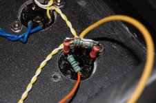
I have taken the tag board out and pulled the wiring off the tube sockets. I tied the resistors for the input to the 6SL7 tube socket (See Picture). I still have to attach a ground wire to run to the star ground.
Is this connected correctly per everyones earlier posts. I just wanted to verify I understood the concept of what everyone was talking about (even it seemed like a no brainer) before I completed the other side and re-installed the tag board. I also added some extra turrets to allow me to get the wires neater and shorter without having so much slack and they will be separated (grouped) better.
Also, Chrish, there was nothing wrong with you saying something about getting the layout right. Yes, I layed the tag board out inline like the schematic, but I know now that I cant take that too literal next time. I just figured that if everything is connected in the correct order, it would work...🙄 I didn't think it would be that critical if I didn't have a resistor connected to the socket, as long the resistor was inline in the correct place in the circuit.
That was a big eyeopener. Oh well, I have to learn some how....
Thanks all...
Brian
Attachments
Nice work. Looks good to me😉
You should also place the gridstoppers on the output tubes right on the socket pin.
You should also place the gridstoppers on the output tubes right on the socket pin.
Just from quickly looking, have you put a 1K resistor to ground from the 2nd grid as suggested before? If so, I would suggest removing and sticking to the original schematic, with the exception of grid stoppers. The suggestion to do this was due to not recognising the paraphase circuit. I would then run the amp without the feedback connected. When that is sorted, connect feedback (and determine if it is the correct phase, if it is not you will have positive feedback, leading to problems).
Regards,
Chris
Regards,
Chris
Good evening
So - We are now going to go with the original input circuit? Take out the 1K and 100K resistors and put the 16v 100uF capacitor and 470K resistor back in?
I'm just making sure before I pull apart the wrong thing.
Also the 1K grid stoppers for the 6V6's are soldered to the tube sockets now, and the signal input + is going to the 10K which is wired directly to the tube socket.
I'll do these mods when I get home from work, just let me know if you see anything else.
Thanks,
Brian
Just following this thread with interest, since it is similar to what I recently put into an amp and like it...It looks like in the picture you have done exactly what SemperFi suggested, that is replace the 16V 100uF capacitor with a 1K resistor. I guess the orange wire is the feedback connection, and as you said the earth still needs to be connected. I hope its OK if a draw a few schematics so we are all clear. The photo then, if I am correct, would be like this schematic1. Although I am new at tubes, I agree that the circuit will hardly work without a cathode resistor, and 10K in the feedback loop will certainly not let enough current flow through the input tube, and agree with SemperFi's suggestion, now, how do I say it, listen to SemperFi and Chris first and me last 🙂 Where I can help is draw a schematic here and there as suggestions are raised so that everyone is on the same page.
Here's a couple more variants for discussion if needed, schematic3 is very close to what I am using with 6L6, no feedback connection though, but sounds good to me, I don't think you'll be disappointed. schematic2 schematic3
Here's a couple more variants for discussion if needed, schematic3 is very close to what I am using with 6L6, no feedback connection though, but sounds good to me, I don't think you'll be disappointed. schematic2 schematic3
Hmmm, at first I interpreted Chris' latest post the same as Brian, and must say I disagree. Where is the path to gnd? (Cathode current)
Then I reread his post...
I believe Chris thought we omitted the feedback to the grid of the phase splitter tube number 2. No Chris, I (or we) have never intended to remove that part, only to place the gridstoppers on the schematic on the pins of the sockets. The 100uF cap should be replaced with a 1kohm resistor.
Actually, for the loop NFB to work, the 100uF cap needs to bypass the 1kohm resistor!!! In other words, all that was really missing was the 1kohm resistro to gnd!!! (The placement of gridstoppers still hold).
Ian444's schematic1 is how I think it should be done, but including the 100uF cap in parallel with the 1kohm resistor. I would find it tempting to build it without the loop NFB to start and then ommit the 100uF bypass cap, and perhaps experiment with a little NFB when it is up and running. Perhaps a 100kohm potentiometer in series with the 10kohm feedback resistor...
If no NFB turns out to be good, I'd end up with circuit2.
Circuit3 will give a little worse phase splitting, so I don't think that would be my first choice.
Last edited:
I feel the last post was a bit unclear. My fault, I didn't pay attention to the loop feedback, which only wants to work on the input tube, and not the other side of the phase splitter.
So to make it 100%: Just like circuit1, but include the 100uF cap in parallel with the 1kohm resistor. That resistor was the only thing missing from the very start!
The grid stoppers should always be as close to the pin as possible, so no harm in fixxing that as well, but it's that 1kohm that does the trick.
Everything else could be as original, though I do feel 100kohms as input resistor is better than 470kohms.
Btw, on Ian's drawing the feedback resistor is 1000, should be 10k...thanks for drawing the schems Ian.
Good Morning All,
I just wanted to try to see if I am keeping up with the conversation. You guys are about 2 levels above me, which is fine since I began this project not knowing much if anything about tubes...
Let me list a couple of things that have been discussed to see if I can make sense of them.
If I need to chill for a few while there is some discussion, please let me know...
1K resistor on input stage that was added. Keep and reinstall 100uF cap in parallel?
100K resistor on input stage. Keep or reinstall 470K per schematic?
Keep all resistors soldered to tube sockets per earlier discussions.
Yes, the feedback ckt. is Orange.
Should I take out the 10K and install a 1K resistor in the feedback loop? Or should I stop today and get a couple of 10K pots.?
Once again, Thanks for all the Help
Brian
This got kinda messy, easy to overlook the details.
You can go ahead and finish the amp per Ian's schematic1, just add the 100uF cap to bypass the 1kohm resistor.
The input resistor as mentioned is rather large at 470kohms though that is a classic value more common in the old days when sources had problems driving lower resistances. Today, espescially with all the HF muck around us, a lower resistance value is more common. It's a matter of taste, and anything from a few kohms to 1megohm can be used. I find 100kohm to be a good compromise for HiFi, and I doubt you will hear any difference between that and 470kohms.
The feedback resistor should be 10kohms. An eventual pot in series can be 10k-1megohm, the higher value, the less feedback. I'd try 100kohm.
Yep got it now.
Looks like, I was working on my port when you were clarifying yours. I'll put this together tonight using one channel to see what happens,then we'll go from there.
Thanks again
Brian
Looks like, I was working on my port when you were clarifying yours. I'll put this together tonight using one channel to see what happens,then we'll go from there.
Thanks again
Brian
schematic4. I would be leaving the feedback disconnected at first just to get the amp running. Good luck!
Ian.
Ian.
schematic4. I would be leaving the feedback disconnected at first just to get the amp running. Good luck!
Ian.
There you go😉 Good job.
You even made the grid stoppers a value I would use, though 10kohms on the input is fine, probably better at rinsing out HF sheit if that were to be a problem.
Good Morning,
Looks good guys, thanks for all the help. I will get the tag board back in tonight, then start working on some of the power supply grounds as mentioned earlier.
I had a little set back so it is taking a little longer. I soldered the 1K gridstoppers inplace then attached all the wires to the output tubes then re-installed the tag board. I started to re-connect the tag board, then it hit me! I installed the gridstopper to the wrong pin. I installed it to pin 8 instead of pin 5. So, I had to fix that. Now I'm ready to re-install the tag board and go forward.
I'll resume building tonight.
Thanks again
Brian
Looks good guys, thanks for all the help. I will get the tag board back in tonight, then start working on some of the power supply grounds as mentioned earlier.
I had a little set back so it is taking a little longer. I soldered the 1K gridstoppers inplace then attached all the wires to the output tubes then re-installed the tag board. I started to re-connect the tag board, then it hit me! I installed the gridstopper to the wrong pin.
I installed it to pin 8 instead of pin 5. So, I had to fix that. Now I'm ready to re-install the tag board and go forward.I'll resume building tonight.
Thanks again
Brian
I had a little set back so it is taking a little longer. I soldered the 1K gridstoppers inplace then attached all the wires to the output tubes then re-installed the tag board. I started to re-connect the tag board, then it hit me! I installed the gridstopper to the wrong pin.
Man I've done that many times, which is why I always have my glass of red wine to help me enjoy those unexpected events that make a quick mod into an all evening task.🙄
Good evening all!
Well, I have to say you guys have given me some great advice on layout and placement of components. By moving the gridstoppers from the tag board to the tube sockets, most of the hum/buzz is gone. 😀
I connected the feedback and the volume and hum/buzz decreased a bit more. I assume that is good negative feedback.😉
I am still getting a low frequency hum (it is not very loud but it is noticable), I am assuming this is a 60/120 hz hum from what I have seen in other posts. I just need to play around with the grounding some to see if anything happens, or possibly convert the heaters to d/c to see if that helps.
One thing I was wondering, I have a spare section left on the 2nd PSU cap. Would it be a good idea install a small value resistor (100R) and create a 4th filter stage and run the input stage off of that. Would the power be that much cleaner?
Let me know if this sounds like a good idea
Thanks again
Brian
One thing I was wondering, I have a spare section left on the 2nd PSU cap. Would it be a good idea install a small value resistor (100R) and create a 4th filter stage and run the input stage off of that. Would the power be that much cleaner?
Thanks again
Brian
...costs nothing to try it apart from 1/4 of an hour of your time...
- Status
- Not open for further replies.
- Home
- Amplifiers
- Tubes / Valves
- 6V6 Hum Issues