Hi,
I have a couple questions about these amplifiers, most specifically:
1. How did you establish that these output transformers are suitable? Are the secondaries also in parallel, or are they in series?
2. At what low frequency does the core saturate, at full power? How much power can they output at say 30Hz without visible distortion of a sine wave?
3. How is the high frequency response?
This is a really interesting idea, to use a power transformer as an audio transformer. Looks like it's possible to save a lot of money this way, I'm curious how well it works.
1 I calculated the Z ratio from the turns ratio. In this case it's 1k3:8R. The secondaries are also in parallel.
2 I can't tell you right now as my scope is acting up, but the input stage clips before the output right now. I'm thinking of adding a 6CG7 driver but I would need to reconfigure the power to get 500 odd volts for it...
3 HF response is flat out to past 50 kHz. 10 kHz square wave looks excellent.
2 I can't tell you right now as my scope is acting up, but the input stage clips before the output right now. I'm thinking of adding a 6CG7 driver but I would need to reconfigure the power to get 500 odd volts for it...
3 HF response is flat out to past 50 kHz. 10 kHz square wave looks excellent.
The reason I ask, is 18V on the secondary is 40.5W into 8 ohms. Now, assuming the transformer is rated for 50Hz, this means at 25Hz it will be good for about 20.25W before core saturation. There would be a tolerance on the transformer, it's unlikely it will saturate at 18V + 15% or so, but that's still only 54W at 50Hz, or half that at 25Hz.
I'm wondering what's special about these specific transformers which allow decent low end response at reasonable power. Maybe they're overbuilt? Some measurements would be very interesting. The idea of discount output transformers is very appealing, even hammond isn't cheap anymore.
50kHz on the high end is amazing - outstanding even.
Last edited:
I have done saturation tests on toroidals used as mains transformers, I will dig out the results and post them later. From memory, saturation (indicated by distortion results) came on quite rapidly at voltages 10-15% higher than rated. Note that for 25Hz you can only have half the voltage compared to 50Hz, which is a quarter the power, not half the power you state above. I think kodabmx might be using a separate subwoofer amplifier for lower frequencies??
I can confirm high frequency response results.
I can confirm high frequency response results.
Note that for 25Hz you can only have half the voltage compared to 50Hz, which is a quarter the power, not half the power you state above.
Right, because the output voltage must be lowered by 1/2, but since the load remains the same, the current also drops by 1/2 making the power 1/4.
This idea isn't as exciting as it first looked! I guess it's the old "when something seems too good to be true, it probably is" thing. Would still like to see some data though, maybe it would work in a system with a subwoofer.
I'll just have to say… KodaBMX's design is quite good at using the now-somewhat-popular, but not so popular, not so long ago Russian valves in a creative, solid manner. We've talked (well … discussed here, on DYI) quite a bit about the efficacy of using high-quality toroidal power-grade transformers in place of Hammond and other even more expensive conventional OTs, and the limited bench-experiments I've done … I confirm: they really do have a place in the equation. Quite nice, actually.
If — for instance — you're not happy with the 25 Hz performance of a nominally 50 VA at 50 Hz transformer, you can always spec the next one up. 100 VA. Or if that's still not enough to lube your rod, well… even larger models at the same ratio will do the trick. You can ALWAYS “get there” with “more iron”.
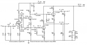
Personally, I'd've drawn up the 3 section diagrams a bit different. But that's just esthetics. The point is, VAS, phase-split, power stage in triode mode, and for kicks, valves in parallel to get the pre-transformer Z low enough.
For all I know, one could very likely change out the 51 kΩ to-ground ballast resistors post-phase-splitter (A1, A2, B1, B2 outputs), to 240 kΩ ea, then drive not 4 output triodes, but 6, 8 or even perhaps 10 of them.
Wicked.
More Iron of course.
Just saying,
GoatGuy ✓
If — for instance — you're not happy with the 25 Hz performance of a nominally 50 VA at 50 Hz transformer, you can always spec the next one up. 100 VA. Or if that's still not enough to lube your rod, well… even larger models at the same ratio will do the trick. You can ALWAYS “get there” with “more iron”.
Personally, I'd've drawn up the 3 section diagrams a bit different. But that's just esthetics. The point is, VAS, phase-split, power stage in triode mode, and for kicks, valves in parallel to get the pre-transformer Z low enough.
For all I know, one could very likely change out the 51 kΩ to-ground ballast resistors post-phase-splitter (A1, A2, B1, B2 outputs), to 240 kΩ ea, then drive not 4 output triodes, but 6, 8 or even perhaps 10 of them.
Wicked.
More Iron of course.
Just saying,
GoatGuy ✓
More iron doesn't help at lower frequencies if it doesn't also come with more turns per volt, which is the case with mains transformers designed for a fixed primary voltage. What will get you to lower frequencies is running the primary at less than 230V rms which implies lower primary impedance if you want power. Hence Goatguy's preference for multiple paralleled output triodes.
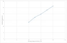
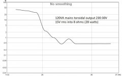
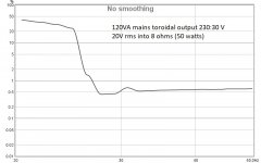
Attached is a plot showing saturation frequency for various secondary voltages into 8 ohms. The output transformer is a 120VA 115+115:30V toroidal, driven by PP mosfet hybrid triodes with B+ of 160V. Voltage at saturation is about 25% higher than what you might expect based on the rated secondary voltage. For saturation at 25 Hz, voltage is about 19V rms, although onset of saturation happens at a lower voltage. The other two plots show distortion for 15V rms and 20V rms vs frequency. Onset of saturation can easily be seen.
Attached is a plot showing saturation frequency for various secondary voltages into 8 ohms. The output transformer is a 120VA 115+115:30V toroidal, driven by PP mosfet hybrid triodes with B+ of 160V. Voltage at saturation is about 25% higher than what you might expect based on the rated secondary voltage. For saturation at 25 Hz, voltage is about 19V rms, although onset of saturation happens at a lower voltage. The other two plots show distortion for 15V rms and 20V rms vs frequency. Onset of saturation can easily be seen.
Attachments
I'm still trying to find a datasheet for the 6P45S that lists the maximum grid leak for fixed bias. I have a feeling it could be as high as 500k or 2M2 for cathode biasing.
If I can get away with using higher grid leak, I can get away with a 6CG7 driver after the PI for more voltage swing. Last test said the VA/PI begins to clip at about 15V output into 6R.
I just need to replace a DC-DC board to get higher voltage. And it's possible that if I give the VA/PI 500VDC instead of 390VDC, it will swing more voltage anyway and not need the 6CG7 driver.
I use no subwoofer at all. Just a pair of Energy RC70 speakers...
I will attempt to get the scope working properly again today and snap a picture of "clipping", but the top of the wave clips, the bottom doesn't which leads me to believe the VA stage is cutting off.
Here's a question for you all:
I've been using triode connection because I prefer the "voltage controlled resistance" rather than "voltage controlled current source", and that I think the low Rp works better with these toroids, but what about tetrode connection?
If I leave the voltage the same (300V-320V) what would you suggest the screen voltage be? 150V?
I assume the drive requirements would be reduced substantially? Right now the output stage wants 140Vp-p for full output. I'm guessing this will be reduced to about 60Vp-p or so?
EDIT: I also found a sheet that says 6P45S can use 500k grid leak in fixed bias so I can increase those from 51k.
If I can get away with using higher grid leak, I can get away with a 6CG7 driver after the PI for more voltage swing. Last test said the VA/PI begins to clip at about 15V output into 6R.
I just need to replace a DC-DC board to get higher voltage. And it's possible that if I give the VA/PI 500VDC instead of 390VDC, it will swing more voltage anyway and not need the 6CG7 driver.
I have done saturation tests on toroidals used as mains transformers, I will dig out the results and post them later. From memory, saturation (indicated by distortion results) came on quite rapidly at voltages 10-15% higher than rated. Note that for 25Hz you can only have half the voltage compared to 50Hz, which is a quarter the power, not half the power you state above. I think kodabmx might be using a separate subwoofer amplifier for lower frequencies??
I can confirm high frequency response results.
I use no subwoofer at all. Just a pair of Energy RC70 speakers...
I will attempt to get the scope working properly again today and snap a picture of "clipping", but the top of the wave clips, the bottom doesn't which leads me to believe the VA stage is cutting off.
Here's a question for you all:
I've been using triode connection because I prefer the "voltage controlled resistance" rather than "voltage controlled current source", and that I think the low Rp works better with these toroids, but what about tetrode connection?
If I leave the voltage the same (300V-320V) what would you suggest the screen voltage be? 150V?
I assume the drive requirements would be reduced substantially? Right now the output stage wants 140Vp-p for full output. I'm guessing this will be reduced to about 60Vp-p or so?
EDIT: I also found a sheet that says 6P45S can use 500k grid leak in fixed bias so I can increase those from 51k.
This is a really enjoyable thread!
If you change to beam power tube mode, the output impedance will rise to the extent you will need some kind of loop feedback to tame it, or the amp will sound terrible.
The drive requirements will be much relaxed, but now you will need more gain to support the negative feedback, and will have to figure out how to make it stable.
Edit: I see that you mentioned in the message that the feedback components just are not shown on the schematic.. sorry about that.
You will have to use the curves to figure out what the optimal screen voltage is. I suggest to regulate this voltage for best results. Something simple like a dropper resistor and an 0D3 or zenor stack is perfectly up to this task.
Last edited:
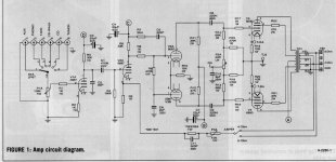
Ok, so since the 6P45S isn't terribly linear as a tetrode, I've decided to continue with triode connection with the following modification to the driver.
I've added a 12SN7 gain stage basically lifted from an RCA manual that used it to drive 6AS7G (100V swings).
I've like to hear ideas/suggestions before I actually build this, but at least it's a pretty easy addition.
Thanks!
I've added a 12SN7 gain stage basically lifted from an RCA manual that used it to drive 6AS7G (100V swings).
I've like to hear ideas/suggestions before I actually build this, but at least it's a pretty easy addition.
Thanks!
Attachments
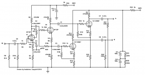
Any way you can direct couple the input stage to the phase splitter? Three sets of coupling capacitors will likely give you problems with low frequency instability.
Attached is a plot showing saturation frequency for various secondary voltages into 8 ohms.
This is interesting.
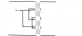
Since his design uses two transformers in parallel, I wonder if it would make more sense to connect them in series instead. It would certainly allow for a lot more headroom at low frequency, and I can't see much in the way of a down side. The ratio could be preserved by connection the secondaries in series too. This would give an allowable primary voltage of 480V at 50Hz before core saturation, and 240V at 25Hz, which is way more headroom than the previous 120V at 25Hz.
Attachments
More iron doesn't help at lower frequencies if it doesn't also come with more turns per volt.....
Actually, a larger core needs fewer turns/volt at the same frequency, so would be good a little lower frequency at the same turns/volt.
But the effect is small, just "more iron" is not an economic path. As you say, adjust the turns per volt considering core size also.
Actually, a larger core needs fewer turns/volt at the same frequency, so would be good a little lower frequency at the same turns/volt.
The manufacturers know this so of course they use less turns per volt with the larger cores 😀
This is interesting.
I have thought of that before but wasn't sure whether the cores not being coupled mattered? I don't know enough to say either way. I've seen a previous suggestion of using a 115+115:115+115 isolation transformer with all windings in series as the primary, then winding another secondary yourself which wouldn't be too tedious.
It's not different electrically from having them in parallel. Both transformers see both halves of the push pull signal and DC balances in both.. I think it should work much better than the parallel connection in this application, because it allows twice as much voltage at low frequency before core saturation.
If you used each transformer separately for the top and bottom push pull halves, and didn't wire it as I showed, then DC would not balance, and performance would be very poor.
If you used each transformer separately for the top and bottom push pull halves, and didn't wire it as I showed, then DC would not balance, and performance would be very poor.
Last edited:
- Status
- Not open for further replies.
- Home
- Amplifiers
- Tubes / Valves
- 6P45S PPP Monoblocks.