You chose to connect your speakers to the 4R tap, but maybe you might like to try them on the 8R tap because speakers present different impedances at different frequencies, and it might sound nicer.
Each one of my speakers consists of two 8-ohm bass drivers in parallel, plus two 8-ohm midrange drivers in parallel, per speaker, so I am not sure why I would ever want to use the 8 ohm tap? My understanding is that it could result in problems for the output tubes???
If they shipped all 560k instead of 470 they would be fine.
All six measure almost exactly 500kΩ. They all are remarkably close to matching exactly. I am going to assume that this is fine unless someone has a different opinion.
Well this is interesting. The directions provided earlier by someone in this thread (thank you!) show two additional resistors that are not included. As long as I am ordering a few small parts, I might as well add 2 of these 100Ω 2W resistors ???
I'm glad that I am going through all of this very thoroughly before I start. I'm waiting for a new multimeter, I'm going to order a few additional parts including a stepped attenuator ($16 - from China of course), I'm going to paint the chassis black instead of silver, and I am waiting to see if the seller actually sends me the missing nut for the speaker binding posts. They said they would, but I'll believe it when I see it. So I am taking this time to thoroughly review - and learn - before I build. I should have 10 days to 2 weeks more to wait.
I'm glad that I am going through all of this very thoroughly before I start. I'm waiting for a new multimeter, I'm going to order a few additional parts including a stepped attenuator ($16 - from China of course), I'm going to paint the chassis black instead of silver, and I am waiting to see if the seller actually sends me the missing nut for the speaker binding posts. They said they would, but I'll believe it when I see it. So I am taking this time to thoroughly review - and learn - before I build. I should have 10 days to 2 weeks more to wait.
Attachments
Did I say something else? Surely I wouldn't chose grid leak resistors that different.
Best regards!
Edit: Related to #80, of course.
Best regards!
Edit: Related to #80, of course.
Why exactly are we supposed to add a 330Ω resistor to the left and right inputs as xraytonyb recommended? How big a problem is this in the real world? I can't remember ever setting a volume control to zero, when xraytonyb said there might be a problem, much less leaving it at zero for very long. I simply turn it off or stop the source playing instead. In fact, I tend to leave it at exactly the same comfortable volume so I don't have to get off the couch to adjust it all the time.
Is this only an issue if the volume pot stays at zero for a period of time? If it's not at zero, I believe xratonyb said the pot would provide sufficient resistance on its own? The kit has been sold this way for 5 years and not changed, so I am wondering why we are adding another component directly in the signal path?
Is this only an issue if the volume pot stays at zero for a period of time? If it's not at zero, I believe xratonyb said the pot would provide sufficient resistance on its own? The kit has been sold this way for 5 years and not changed, so I am wondering why we are adding another component directly in the signal path?
Attachments
Which resistors exactly were you referring to? I didn't find any in the schematics.
Btw, those 1k resistors to the EL84 grids really don't need to be rated at 1W...
Best regards!
Btw, those 1k resistors to the EL84 grids really don't need to be rated at 1W...
Best regards!
Which resistors exactly were you referring to? I didn't find any in the schematics.
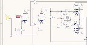
They are not there. Xraytonyb said to add them. See attached for clarification of where he said to put them.
Attachments
Btw, those 1k resistors to the EL84 grids really don't need to be rated at 1W...
I guess I'll use what's in the kit. I can replace them with genuine top-quality metal film resistors for $3.50, or less if they don't need to be 1 watt. I will say that the ones in the kit are all very precisely matched, like 1% or less. I have bad memories of resistors burning up on my Dyanaco ST70 series ii whenever a tube went bad, so a little overkill is fine with me.
I want to see just what this little amp can do, so I am upgrading a few things here and there, especially the volume pot. Xraytonyb used an ALPS that he had on hand, but the specs on those are terrible compared to a stepped attenuator, and I can get one of those for the same price.
Now, if I can JUST get the seller to send the missing nut for one of the speaker binding posts. I'll file a complaint and negative feedback if they don't ship it soon. I really don't want to have to replace those and have no idea what nut might work. 😡 I KNOW at one point I had a spare pair of binding posts with a nut that might work, but I cannot fin them anywhere, and I have looked through every one of my parts boxes three times. Sigh.
Oh, the resistors as suggested do the same thing as those in the EL84 grids. They prevent possible oscillations. Anyway, as an ECC85 triode doesn't show a transconductance as high as the EL84's, they aren't really needed.
Best regards!
Best regards!
Anyway, as an ECC85 triode doesn't show a transconductance as high as the EL84's, they aren't really needed.
Excellent. Xraytonyb said as long as the pot wasn't at zero, there would be no problem. So, I think I'll take that route. I would never turn it all the way down anyway. I'd just hit stop or pause on the CD.
And ... nobody has been able to answer this question in another thread about wiring and voltage ratings:
I'm surprised nobody has any thoughts on 350-400 volt wire insulation. I'll bet a lot of people have used common US wiring (old extension cords, hookup wire, etc.) that they had in a project box (like my wire rated at 300 volts), but I don't want to be the one to have an arc inside my amplifier and then have to fix the mess. When working on an old Fisher tube stereo receiver many years ago, I don't recall seeing any special wiring.
I can order 600 volt silicone insulated wire that is quite nice, but I am wondering if it's overkill for the short 350-400 volt runs inside the chassis of a tube amp.
The 22 AWG wiring that comes in the kit is pretty weak and has very poor insulation, but I'm not just talking about this little kit, I'm talking about future projects. This one is intended to be my first learning experience. Plus out of curiosity I want to see just how well this simple little amp can perform.
I never used the wire supplied on this kind of kits, exactly because I don't trust the long term stability of the insulation. I use brand name 20AWG or 22 AWG solid core wire such as Alpha Wire 1561 WH005. 20AWG is sturdier and easier to work with. Solid core wire stays put where you place it, and does not need to be fastened to the chassis like a silicone wire. A cheaper option are some solid core wire kits from China. I've also used them, but I test a sample with a megger (insulation resistence tester) set to 1000V before use. You will need also a few keystone 819 terminal strips (or the China knockoffs). Before painting the chassis, try a sample (maybe the bottom).
Before painting the chassis, try a sample (maybe the bottom).
I will. I have an airbrush if needed, but high quality satin black spray paint should work fine. I have to wait for low humidity though. Painting in high humidity never works well. I can put a piece of black paper over the silver front panel if it bothers me or go for the total stealth blackout and paint that too. 😉
I'm going to go with the 300 volt rated wire that I already have on hand unless someone tells me that I'm liable to have a problem because actual voltage is supposed to be 350. The insulation is excellent quality.
The instructions indicate that the filament wires should be run down the same side as the input signal and negative feedback wires, which is contrary to my expectation. It seems like the flament wires and AC power should go down one side and the signal down the other? The output goes down the center away from both.
As a novice just getting back into this after many years, I wanted to see the entire schematic all in one place. Does this look correct? The voltages in red are the ones specified in the directions.
Also - is anyone but me concerned about running the 6P14 or EL84 output tubes at 300 volts, which appears to be the maximum voltage for both tubes? Isn't this going to just eat up the tubes very quickly? I don't want that. The kit comes with what is labeled a "spare" zener diode that is 91 volts per the label instead of 100 volts. That's in there to reduce this voltage, correct?
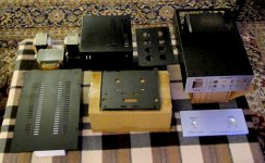
I disassembled and very carefully painted everything but the front panel and the rear panel satin black, including the screws, to reduce the visual impact. I bought plugs to fit the holes where the magic eye tubes were supposed to be. I do custom decal work, so I am having the words "Power" and "Volume" printed in white so I can paint the front panel black too. It's a multi-step process to do the decals right and prevent yellowing over the years, with multiple clear coats to seal them, but it's a small piece. Paint will improve the sound, right? 🙂
Also - is anyone but me concerned about running the 6P14 or EL84 output tubes at 300 volts, which appears to be the maximum voltage for both tubes? Isn't this going to just eat up the tubes very quickly? I don't want that. The kit comes with what is labeled a "spare" zener diode that is 91 volts per the label instead of 100 volts. That's in there to reduce this voltage, correct?
I disassembled and very carefully painted everything but the front panel and the rear panel satin black, including the screws, to reduce the visual impact. I bought plugs to fit the holes where the magic eye tubes were supposed to be. I do custom decal work, so I am having the words "Power" and "Volume" printed in white so I can paint the front panel black too. It's a multi-step process to do the decals right and prevent yellowing over the years, with multiple clear coats to seal them, but it's a small piece. Paint will improve the sound, right? 🙂
Attachments
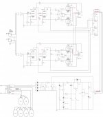
I hope that I have the combined schematic in the previous post correct.
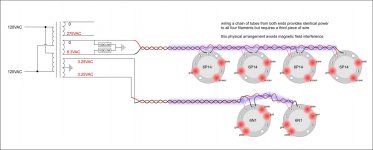
Does anyone disagree with this filament wiring arrangement? It's the best I can come up with based on comments I have found online and a YouTube video about routing the wires. It involves running one wire to the near end of a chain of tubes, and the other wire runs to the far end of the chain of tubes and then comes back.
Does anyone disagree with this filament wiring arrangement? It's the best I can come up with based on comments I have found online and a YouTube video about routing the wires. It involves running one wire to the near end of a chain of tubes, and the other wire runs to the far end of the chain of tubes and then comes back.
Attachments

There's no reason to use a third wire.
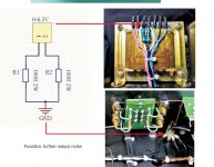
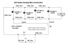
I'll see if I can find the sources of that info again. They might have been on this forum. I actually saw it more than one place. In theory, wiring them the "normal" way results in less power arriving at the last tube in the chain. Routing one wire to each end and then running one back would solve that problem, if it's real. Can't believe everything you read, but it makes sense. Diagram attached showing the resistance that the wires would add. He assumes 22 AWG wire, which is what came with the kit. I suppose the problem would be virtually eliminated with heavier wire. I do have 20 AWG, and I was planning to use it. I don't think I have any 18 AWG.
Yes, I know about the twisting, but according to this video it still can be a problem (timestamped):
Attachments

Last edited:
Good video. It shows that the untwisted part of the wiring causes issues, and is without a third wire.
All good fortune,
Chris
All good fortune,
Chris
Perhaps I haven't been clear. I have two totally different questions:
- The routing and twisting - the video seems pretty clear about that unless it's wrong.
- Whether it is a valuable approach to wire a string of tubes from both ends per the schematic attached, which would require three wires to do assuming the filament wires for all four tubes run down one side of the amplifier. If using 22 AWG wire, it appears that the last tube in the string gets significantly less power to the filament unless the "correct" approach in the schematic is used.
Attachments
- Home
- Amplifiers
- Tubes / Valves
- 6P14/EL84 amplifier kit building questions - before I build - maybe during if I do