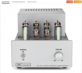
Ok, I bought a kit.
The seller I was dealing with in China finally updated the pictures to the current version without the loudness circuit, so I should be receiving the new version. After all of the nickels and dimes and fees and taxes the total was $358.01. Some sellers are trying to get almost $500 and prices seem to rise daily.
I hope this works. Fingers crossed.
Now we wait to see what's actually in the box because younever know with these things ...
With much cursing and swearing and backache, I pulled my Emotiva A/V processor-preamp out of my system and boxed it up. I pulled my 80-lb Outlaw Audio 5 channel amplifier out of my system and boxed it up. Neither has ever satisfied me. Do you have any idea how much dust builds up behind a system that has not been moved in 10 years? I have no preamp, so I had to pull my Dynaco Stereo-70 series II out too. That leaves me with a freebie Denon A/V receiver for now. I hope this all works out.
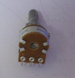
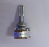
I want to get back to tubes, and I hope this little amplifier is a good start. It will be a learning experience to update my antiquated skills and knowledge, and maybe a way to gain confidence to do other projects. It also might actually sound good (I hope)! I will examine the option to wire it point-to-point, and I have no intention of using the magic eye tubes, but I won't know if point-to-point is a realistic option until I have the actual parts and the board in my hands. Some of the components designed for PC board mounting might have to be swapped out. It looks like it comes with a garbage potentiometer, but so did most things that sounded just fine in the heyday of tubes. Only one way to find out. I can always change it. That's the beauty of DIY.
The seller I was dealing with in China finally updated the pictures to the current version without the loudness circuit, so I should be receiving the new version. After all of the nickels and dimes and fees and taxes the total was $358.01. Some sellers are trying to get almost $500 and prices seem to rise daily.
I hope this works. Fingers crossed.
Now we wait to see what's actually in the box because younever know with these things ...
With much cursing and swearing and backache, I pulled my Emotiva A/V processor-preamp out of my system and boxed it up. I pulled my 80-lb Outlaw Audio 5 channel amplifier out of my system and boxed it up. Neither has ever satisfied me. Do you have any idea how much dust builds up behind a system that has not been moved in 10 years? I have no preamp, so I had to pull my Dynaco Stereo-70 series II out too. That leaves me with a freebie Denon A/V receiver for now. I hope this all works out.
I want to get back to tubes, and I hope this little amplifier is a good start. It will be a learning experience to update my antiquated skills and knowledge, and maybe a way to gain confidence to do other projects. It also might actually sound good (I hope)! I will examine the option to wire it point-to-point, and I have no intention of using the magic eye tubes, but I won't know if point-to-point is a realistic option until I have the actual parts and the board in my hands. Some of the components designed for PC board mounting might have to be swapped out. It looks like it comes with a garbage potentiometer, but so did most things that sounded just fine in the heyday of tubes. Only one way to find out. I can always change it. That's the beauty of DIY.
Attachments
Last edited:
I can send the instruction to anyone interested. Just PM me.
Thanks so much! After considerable work, I have translated the Chinese directions for the new version of the amplifier to English. It was a whole lot of work, but I am glad I did it because the directions contain a lot of information that I would not have gotten from the pictures alone. Unfortunately, the 67 page file is too large to upload here, even in small 10-page zip files.
I would like for someone who is interested to review the new instructions for errors and any obviously bad practices. Anyone who wants a copy, please let me know.

What format is the file? I usually find if I can print to PDF, then attach the PDF.Thanks so much! After considerable work, I have translated the Chinese directions for the new version of the amplifier to English. It was a whole lot of work, but I am glad I did it because the directions contain a lot of information that I would not have gotten from the pictures alone. Unfortunately, the 67 page file is too large to upload here, even in small 10-page zip files.
I would like for someone who is interested to review the new instructions for errors and any obviously bad practices. Anyone who wants a copy, please let me know.
Can you upload it to dropbox, Google Drive or OneDrive (or similar 'cloud' location), make that file public, and post the location URL?
Might be able to divide it up into 2 or 3 sections, then use winzip for each section. I'm not sure what file size limit is here, maybe a mod could provide info?PDF 67 pages, 28MB.
Jim
The Chinese original can be downloaded from here: https://drive.google.com/file/d/1S_Yz822MBgqkhp78-bDIAKwqcYnHMlps/view?usp=sharing
And the translated instructions: https://drive.google.com/file/d/1iew0VAYs33ILgaCrBOqd0biVfyMwWUHl/view?usp=sharing
And the translated instructions: https://drive.google.com/file/d/1iew0VAYs33ILgaCrBOqd0biVfyMwWUHl/view?usp=sharing
Thank you tbaashus! I'd like to see if anyone has any comments on the new directions and the revisons since they removed the loudness circuitry. I was impressed with the level of detail in the 67 pages of instructions. If anyone has trouble downloading let me know.
One curious thing that I noted is the comment on page 12 of the translated instructions that a 5H250mA choke can be used in place of a resistor on the power supply. I don't see any way that could be mounted on this amplifier chassis. It looks like a large and heavy part.
Given the low power (11 watts/channel), and some distortion of the waveform noted by xraytonyb below 35 Hz, I am concerned about the deep bass being light on this amplifier, so anything anyone sees that might improve the bottom end, please let me know before I start. I don't know how much negative feedback this amp is using, but sometimes that cleans things up at the bottom end, albeit at the expense of the midrange sometimes.
Now I wait for it to ship from the seller in China. The payment cleared so I'm waiting for a tracking number.
A 5H 250mA choke will be big and hard to accommodate in the chassis. I've found the Hammond 156R, 1.5H 200mA to work effectively in my EL84 builds. Not expensive and fairly compact.
S.
S.
Here is everything I have been able to find over the past week about the tubes used in this amplifier, including Chinese and Russian translations and vintage tube spec sheets. If anyone has any improvements or corrections to any of these documents, please let me know.
You might want to download a copy because a number of other amplifiers use these same tubes.
You might want to download a copy because a number of other amplifiers use these same tubes.
Attachments
Well, it's here. Only 6 days from the day I ordered to my doorstep via DHL. 🙂
Impressions:
1) My speakers are 4 ohms, they have been 4 ohms for 30 years, and they will continue to be 4 ohms forever after I repower them with new drivers that I bought over the summer. So, why shouldn't the negative feedback wire be attached to the 4 ohm tap instead of the 8 ohm tap? Would the resistor need to be changed?
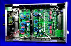
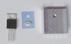
2) The installation of the large power supply transistor (voltage regulator?) on the heatsink isn't mentioned in the directions. See attached picture. It looks like there is a thin film that goes between the transistor and the heatsink. Also, there seems to be a tiny insulator that fits exactly in the hole in the transistor (voltage regulator?). Is this correct? Is this to prevent the heatsink from having 275V on it? If so, this insulation, especially the thin film, seems awfully flimsy.
3) I'm not sure of the quality of the included volume pot. It looks pretty cheap. Any thoughts on upgrading that? If I'm going to the trouble of building, I might as well upgrade a few things to make sure they are as good as reasonably possible, and I don't want to have any problems later.
Impressions:
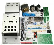
- It looks like some of the included wiring would benefit from upgrading, which xraytonyb mentioned in his build videos. It's all quite a small gauge. I have an assortment of slightly heavier wire in multiple colors from Remington that I will use between the output transformers and the speaker terminals. For things like the filament wiring and the high voltage wiring, I suppose it doesn't matter and the smaller wire provided will be easier to work with.
- I'll use better wires for the input signal because the included signal wire is inadequate, and I'll solder them instead of using the included plugs and jacks.
- The fit and finish (silver paint) on the chassis is flawless, as is the black silkscreening on the silver front panel. However, I hate the silver color and may paint the whole chassis black before I start, although that doesn't solve the "problem" of the silver front panel, which is great quality if you like silver.
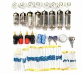
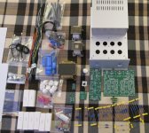
- All of the components appear to be here, but I haven't tested the resistors yet.
- I wish I had a meter that would test the caps, but I don't. The .22uF caps included are ±10% and ideally I'd match the four that are in the signal path as closely as possible. My multimeter is really, really old. Maybe I'll finally buy a new one that can test caps, unless there is some other way to match them.
- The seller emailed the wrong schematic, and the schematic in the box doesn't show the magic eye tubes. The seller also sent only the first few pages of the manual, with zero assembly instructions. The seller's communication via AliExpress has been terrible. Fortunately, I have the full directions thanks to members of this thread, and thankfully all of the components seem to be here.
1) My speakers are 4 ohms, they have been 4 ohms for 30 years, and they will continue to be 4 ohms forever after I repower them with new drivers that I bought over the summer. So, why shouldn't the negative feedback wire be attached to the 4 ohm tap instead of the 8 ohm tap? Would the resistor need to be changed?
2) The installation of the large power supply transistor (voltage regulator?) on the heatsink isn't mentioned in the directions. See attached picture. It looks like there is a thin film that goes between the transistor and the heatsink. Also, there seems to be a tiny insulator that fits exactly in the hole in the transistor (voltage regulator?). Is this correct? Is this to prevent the heatsink from having 275V on it? If so, this insulation, especially the thin film, seems awfully flimsy.
3) I'm not sure of the quality of the included volume pot. It looks pretty cheap. Any thoughts on upgrading that? If I'm going to the trouble of building, I might as well upgrade a few things to make sure they are as good as reasonably possible, and I don't want to have any problems later.
Attachments
Last edited:
A few minor issues popped up as I went through everything.
1) One of the speaker binding posts is missing 1 of the 4 gold nuts that holds it and the terminals in place. The AliExpress seller is being very difficult to deal with, but I can have AliExpress intervene if needed. They will need to mail me the part. This is the worst seller I have ever dealt with, and I have been using AliExpress for many years.
2) One of the power supply caps is different, branded Philips, and appears to be 1998 production. I asked about it in another thread to try to confirm the age.
I'll bet the one Philips cap is 1998 production. The other caps are all branded Vishay BC. Doing some reseach, I found these tidbits:
3) R1, R2, R13, R14, R15, and R16 are odd. I tested all of the resistors in the kit, and all were spot on except these six. They test at 500kΩ but are marked 570kΩ with their color bands. They are supposed to be 470kΩ according to the schematic. Should I spend a couple of bucks and replace them?
1) One of the speaker binding posts is missing 1 of the 4 gold nuts that holds it and the terminals in place. The AliExpress seller is being very difficult to deal with, but I can have AliExpress intervene if needed. They will need to mail me the part. This is the worst seller I have ever dealt with, and I have been using AliExpress for many years.
2) One of the power supply caps is different, branded Philips, and appears to be 1998 production. I asked about it in another thread to try to confirm the age.
The date code on the capacitor is KO. Philips marks their capacitors with a date code
according to IEC 62. This date code repeats every 20 years. So the capacitor is
either October 2018, or October 1998.
I'll bet the one Philips cap is 1998 production. The other caps are all branded Vishay BC. Doing some reseach, I found these tidbits:
- BC components, a leading manufacturer of passive electronic components, emerged from Philips Electronics Components division in January 1999.
- Vishay acquired BC components in December 2002. The former BC components product portfolio is now divided into Vishay Beyschlag and Vishay BC components.
3) R1, R2, R13, R14, R15, and R16 are odd. I tested all of the resistors in the kit, and all were spot on except these six. They test at 500kΩ but are marked 570kΩ with their color bands. They are supposed to be 470kΩ according to the schematic. Should I spend a couple of bucks and replace them?
Attachments
Old Philips caps should always be considered suspect. They are the only major brand I‘ve had go bad just sitting in a bin in a temperature controlled shop. Leaked goo all over.
The 470k resistors are not critical, but be sure the four that go to g1 on the output tubes are the same since they will affect loading on the phase splitter. Exact value not critical but equal value is.
The 470k resistors are not critical, but be sure the four that go to g1 on the output tubes are the same since they will affect loading on the phase splitter. Exact value not critical but equal value is.
Well, it's got a Cathodyne phase inverter, doesn't it? This per se has very different output impedances, hence different loading within the usual differences doesn't matter that much. The power tubes' properties may vary much more.
Bst regards!
Bst regards!
Does the gauge of the wire on this side of the output transformer matter at all? It looks like it's connected to 350 volts from the power supply (full schematic is in earlier posts), so I assume current must be minimal since it's only a 12 watt per channel amp. I'm looking at the wire in the Chinese kit, and almost all of it is really thin, 22 AWG as best I can tell by comparing it to other 22 AWG wire that I have. I am going to beef up the wire between the output transformers and the speaker binding posts. I have plenty on hand, and 22 AWG is afwully thin.
Attachments
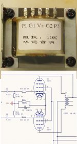
Also, since I will only be using the 4 ohm outputs, why is the negative feedback connected to the 8 ohm output? That never has made any sense to me. Nothing will ever be wired to the 8 ohm output as long as I own the amp. It seems like it would just make sense to connect it to the 4 ohm output, but I have no idea what effect that would have on the circuit.
There are voltages generated on both the 4R and 8R windings of the OPT. You chose to connect your speakers to the 4R tap, but maybe you might like to try them on the 8R tap because speakers present different impedances at different frequencies, and it might sound nicer.
The designer chose the 8R tap for calculating the amount of voltage to NFB.
The designer chose the 8R tap for calculating the amount of voltage to NFB.
The output impedances are different, but the relative gain between the top and bottom is directly related to the ratio. You wouldn’t want to load one side down with 220k and the other with 470k, even though either would work for grid bias. Resistor tolerance is splitting hairs. If they shipped all 560k instead of 470 they would be fine. If they shipped half and half I’d match pairs or go digging for another pair that matched the first.Well, it's got a Cathodyne phase inverter, doesn't it? This per se has very different output impedances, hence different loading within the usual differences doesn't matter that much. The power tubes' properties may vary much more.
Bst regards!
You also don’t want to encourage differences in say grid leakage current from upsetting the balance either. If you use the same R, there is less statistical spread than if you used different R.
You could trim the resistors for AC balance, resulting in different resistances. But change the tubes and you’d have to do it again.
- Home
- Amplifiers
- Tubes / Valves
- 6P14/EL84 amplifier kit building questions - before I build - maybe during if I do