Generalizations . . .
A small output transformer can be a mystery.
It certainly has limited laminations, can saturate early.
The primary and secondary may, or may not be interleaved.
There may be lots of turns, so a given DC current will saturate earlier than with less turns.
It is according to (Amp x Turns) versus Laminations.
More turns, more Amps, or both needs more laminations.
But not enough turns will cause the inductance to be lower, and the low frequencies to roll off early (but at least not be saturated as early, only will cause the tube load line to have more distortion because the slope is steeper for low frequencies.
But that is a simple explanation, because the load line there is elliptical, not straight.
There are tradeoffs, so not all transformers of the same size have equal performance.
High frequency, low frequency, saturation, etc.
Suppose you design the amp circuitry to have low frequency rolloff before the output tube.
That reduces saturation that low frequencies would have caused to the transformer.
Not all loudspeakers require the amp to be flat to 20Hz (some will argue the point).
We are not creating a world class system if we use small output transformers.
Suppose you decide not to use global negative feedback, so the saturation will not be exponentially increased by the correction signal that the feedback applies at low frequencies.
Using negative feedback or not somewhat depends on the output mode you will use.
Pentode Beam Power modes requires negative feedback.
UL mode requires less negative feedback.
Triode and Triode wired mode requires the least negative feedback.
But the mode also affects maximum output power, harmonic distortion, damping factor.
Understand one concept real well. Then understand the next concept real well, etc.
Looking at all of them at the same time usually requires almost reflex knowledge of all of them, and how they interact with each other.
A small transformer’s windings might be really well designed, so negative feedback in pentode & beam power modes might be easy to apply and compensate negative feedback.
Other small transformers not.
Then we have the Amp x Turns and laminations that affect low frequency performance.
Might be OK to use negative feedback, or may not be a good idea.
For a small transformer, it could be just fine for UL.
But the most forgiving mode is most likely the Triode and Triode wired modes; just do not expect very much output power versus both UL and Pentode / Beam Power modes.
Good question about triode giving up sound quality. I was a little sleepy.
What you give up is output power. If you need the power of a UL, Pentode, or Beam Power mode, the sound quality you give up will be when you clip the triode amp to get the same output power.
When you talk about grounding the 4 Ohm tap, and connecting the cathodes to the Common and 16 Ohm taps, you are talking Push Pull, not single ended.
You have to settle on using either Push Pull or using Single Ended.
The performance, the rules and the generalizations change from PP to SE.
Push pull transformers do not have to be as big as single ended transformers.
I think you have been jumping back and forth between SE and PP.
I thought this was SE, but then you mention cathode feedback for PP.
Most designs that employ small output transformers can please many customers, depending on their speakers, room, and other factors (some are never pleased with high end systems, and keep trying other high end systems).
Generalizations are just that.
There are lots of genius designs that make the best use of parts, because of judicious selections of what to tradeoff, and what specs are paramount for a specific system.
At some point, you have to try something, or abandon those parts, circuit, or some other thing,
And move on to a completely different solution.
If you expect the first try to be optimum, then first you must set the rules, and the target to hit.
I am not sure what to tell you.
A small output transformer can be a mystery.
These are the only informations that I have by now.
Code:
1. Power: 3W

2. Frequency Response: 20z-30KHz (-2dB)

3. Core Specifications: EI48X24, core section X24MM

5. Primary Impedance: 5.5K Ω,

6. Secondary: 0-4-6-8 Ω and UV level meter use

7. Primary Inductance: 11H

8. Primary resistance: 278Ω

9. The primary current: 70MA

10. Grade resistance: 2.3 Ω
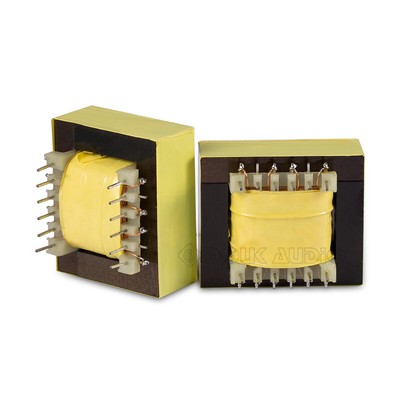
11. Weight: 0.6kg / pcsBy looking at this photo, I would say it is interleaved P-S-P-S-P.It certainly has limited laminations, can saturate early.
The primary and secondary may, or may not be interleaved.
Thanks, so I could consider to roll-off a bit earlier with the coupling cap in order not to overload the OPT and improve the results on the available bandwidth.Suppose you design the amp circuitry to have low frequency rolloff before the output tube.
That reduces saturation that low frequencies would have caused to the transformer.
This is one of the reasons I would like to try shunt feedback: I've tried it with UL and together with a small amount of cathode feedback and I like the way it sounds. Well, at least I've found one of the ways it can sound good, for sure not the best, as I'm not experienced in this.Suppose you decide not to use global negative feedback, so the saturation will not be exponentially increased by the correction signal that the feedback applies at low frequencies.
That I absolutely don't have. I know.Looking at all of them at the same time usually requires almost reflex knowledge of all of them, and how they interact with each other.
I'm going through the sea like Columbus, without knowing exactly what I'm doing, instead of having a Vasco de Gama approach through known "ports".
Being so cheap I would propend for the latter.A small transformer’s windings might be really well designed, so negative feedback in pentode & beam power modes might be easy to apply and compensate negative feedback.
Other small transformers not.
Thanks for explaining this, perfectly clear!Good question about triode giving up sound quality. I was a little sleepy.
What you give up is output power. If you need the power of a UL, Pentode, or Beam Power mode, the sound quality you give up will be when you clip the triode amp to get the same output power.
Yes, it was a PP, in this case I would ground 0 or 8 and connect the cathode to the other side, depending on the phase of the signal.When you talk about grounding the 4 Ohm tap, and connecting the cathodes to the Common and 16 Ohm taps, you are talking Push Pull, not single ended.
You are right, this is SE, I was just reporting my experience with cathode feedback in PP.I think you have been jumping back and forth between SE and PP.
I thought this was SE, but then you mention cathode feedback for PP.
I actually have a class D amp, a EL34 based PP, I'm finalising the BH EL84 and this SE project for the winter.Most designs that employ small output transformers can please many customers, depending on their speakers, room, and other factors.
I don't expect it, as I know from some hundreds hours soldering different parts to get the sound I wanted in instrument amps, that first hit is not the right one. Most of the times. But experience helps coming closer and understand why.If you expect the first try to be optimum, then first you must set the rules, and the target to hit.
Thanks as usual 6A3sUMMER!
Last edited:
I found this datasheet, not sure if you had seen it.
6p13c
What is your main goal with this experiment? Are you looking to get the best out of those components, explore the impact of changing topographies, or work out how a cheap kit can be embellished to take it to the next level (for instance upgrading components)?
6p13c
What is your main goal with this experiment? Are you looking to get the best out of those components, explore the impact of changing topographies, or work out how a cheap kit can be embellished to take it to the next level (for instance upgrading components)?
Assuming that a 6p13c is similar to an EL36, apart from the tougher screen grid, there are some interesting musings here, with zero bias, and 35v on the screen ...
EL36 experiments
EL36 experiments
The 6P13S tube is NOT similar to the EL36 tube in terms of electrical characteristics, it just looks like it!
Thanks OldHector!I found this datasheet, not sure if you had seen it. 6p13c
Primarly the first two, then the 3rd: see the limits of a cheap solution (how good it could sound without any price increase), then consider the sonic impact of better (not esoteric) OPTs.What is your main goal with this experiment? Are you looking to get the best out of those components, explore the impact of changing topographies, or work out how a cheap kit can be embellished to take it to the next level (for instance upgrading components)?
You mentioned getting the sound you wanted for a Guitar amp.
Is the current project for a Guitar amp?
Or, is it for a Hi Fi amp.
Guitar Amps are designed "to a particular sound, or range of sounds" Yes?
Typically Hi Fi amps are designed to reasonable accuracy in the system they will be used in. Some want to purposely tune their system, or even tune it away from accuracy.
I have no idea what grade resistance is.
You are not going to get a lot of performance out of a SE transformer that is 0.6kg (1.32 lBs).
The purpose of rolling off the low frequencies from the driver is to keep the low frequencies out of the output tubes and therefore from the cheap transformer.
Not only does that help reduce the chance of saturation, it also reduces the Intermodulation Distortion of mid and high frequencies that would occur if the core was saturated (the bass frequencies become sideband signals on the mid and high frequencies. And when the core is saturated, the load impedance on the output tube increases, causing distortion of the signal that causes the saturation..
The bass will be weaker, but at least might not saturate the core (causing the multiple problems that brings).
Unfortunately, even if you do not use Global negative feedback from the OPT (Output Transformer) secondary (and that includes Cathode feedback from the secondary); then when large low frequencies are applied to the OPT Primary, the core becomes saturated, and the primary inductance is reduced.
That effect may be slightly less, but is still there, with all the problems that saturation causes.
So, the project your questions are about is to help develop a single ended EL84 amp, Right?
Last edited:
The current project is a Hi Fi SE stereo amp with 6P13S output tubes. I talked about guitar amps because I've built many of them, most of them under my design, but there the purpose is very different.You mentioned getting the sound you wanted for a Guitar amp. Is the current project for a Guitar amp? Or, is it for a Hi Fi amp.
Yes, approximately they have a very specific sound, because they have particular sequences of stages that are designed to generate a certain "pattern" of harmonics (most common is two center biased stages, followed by a very cold biased stage, then a center/warm biased stage and then a cathode follower that smooths one side of the sinewave. Then there are other variants (some of them all center biased). Apart from the polarizations, the other "trademark" of each guitar/bass amp is the way the frequency is limited and how much in every different stage (generally speaking: lows to avoid confused sound, and high to avoid harsh sound).Guitar Amps are designed "to a particular sound, or range of sounds" Yes?
Thanks, I will test it on two different cabs, one is Klipsch RF82 and the other one is an Aliante.Typically Hi Fi amps are designed to reasonable accuracy in the system they will be used in. Some want to purposely tune their system, or even tune it away from accuracy.
If you see the sequence of information, just before that they report primary resistance and current, so it is just a wrong translation of secondary resistance. So Damping will never exceed 3.5I have no idea what grade resistance is.
Thanks, indeed after trying to get the best out of it as is (as I was saying, trying to know where a kit like this one could go without extra price), those ones will be the first upgrade I'd do.You are not going to get a lot of performance out of a SE transformer that is 0.6kg (1.32 lBs).
Thanks again, very clear.When the core is saturated, the load impedance on the output tube increases, causing distortion of the signal that causes the saturation..
When large low frequencies are applied to the OPT Primary, the core becomes saturated, and the primary inductance is reduced.
It's a 6P13S SE project. It was the cheapest octal kit I've found.So, the project your questions are about is to help develop a single ended EL84 amp, Right?
OTs are very small. They will distort less 70 Hz. You need OTs about 20-30 W and more, because current will be about 60 ma for good sounding/.
/this is my SE 6BQ6 /6П31С/. If second grid is with 200 V, sounding is more sharp. I use about 170 V/. The sound is very close to 2A3.
/this is my SE 6BQ6 /6П31С/. If second grid is with 200 V, sounding is more sharp. I use about 170 V/. The sound is very close to 2A3.
Attachments
Thank you azazello, but I have 6П13С/6P13S tubes. I won't expect more than 5 Wrms with good OPTs, so way less with the included ones.this is my SE 6BQ6 /6П31С/.
You can use 6P13S with Pa about 17-18 W /not 12-13 acc. specification/, without problems. For good sounding tube current no 40-50 ma, but 60-65 ma with U about 260-300 V. /65 ma with 260 V, and 60 ma with 280-300 V/. 6P13S and 6P31S are almost the same with 2 different legs.
Last edited:
Thanks again azazello,
I've receipt the package: they are 6P13P, chinese version of russian's 6P13S (https://frank.pocnet.net/sheets/095/6/6P13P.pdf).
I'm not sure how they can support 18W Pa and I would keep them within their limits.
As for the analogy between '31 and '13, I would say no based on the data found online and this post:
Those Magnificent Television Tubes
The reason why I'm tempted touse CFB on these amps is that I often read comments like this: DIY McIntosh Amp
I will give it a try, now being also awarded by 6A3sUMMER.
In a single ended amplifier (CFB) can make some cheap OPT's sound bigger than they really are and improve their bass response. If the OPT has design issues (unintentional, or intended for cost reasons) the cathode feedback may not offer an improvement, but rarely causes serious problems unless it is inadvertently applied with the wrong phase.
I will give it a try, now being also awarded by 6A3sUMMER.
I meant warned obviously, but I can no more edit the message.awarded by 6A3sUMMER.
The OPTs I've receipt are declared as 5.2 kOhm and 0-4-8 Ohm.
I'm thinking to supply it through a dcdc converter first for B+ and use fixed bias.
I think the working point will be around 270-280Vdc with 45-50 mA at idle.
I will also use a dedicated variable voltage power sepply for screens, in order to find the best one, then fix it with one (or two in series) zeners from cathode to screens.
What do you think?
That was the idea, but it seems to me that suggested voltages are wrong.
It suggests 280 Vac with 300 Ohm as a CRC filter and 300 Ohm cathode resistor.
It means 370 Vdc B+ approximately across the tube, that is too high even for PP.
So the "as-is" seems not to be an option.
Do you agree?
It suggests 280 Vac with 300 Ohm as a CRC filter and 300 Ohm cathode resistor.
It means 370 Vdc B+ approximately across the tube, that is too high even for PP.
So the "as-is" seems not to be an option.
Do you agree?
- Home
- Amplifiers
- Tubes / Valves
- 6P13S SE cheap amp: improvement suggestions