Sorry about if mu post about the mu vs. gain,
was like a lesson. I didnt meant to patronize at all...😛
just a few words about, i was not mark clear enough
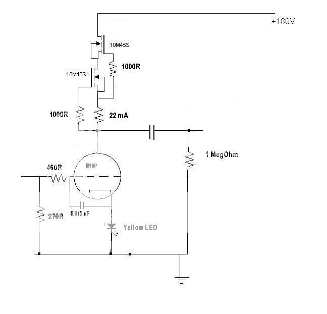
internal parameters values, in first picture.
.
was like a lesson. I didnt meant to patronize at all...😛
just a few words about, i was not mark clear enough
internal parameters values, in first picture.
.
With the same circuit parts, like on the SCH for the example,
You can always expect that the stage gain
will gravitate to the mu of tube in point
CCS,
L load,
R load,
Transformer Rload value 1:1 load
with that order close to the mu of the tube
😀
.
But that is not from the first importance,
more is that the sound result is different
and everyone should pick the topology according to personal
taste and accessibility for the needed parts and power supply for.
.
I will try to put together some results of theese 4 different load types
for this 6N6P circuit.
And Yes, Your measurements are right, the mu and gain are little bit smaller then those given in datas, for those small triodes.
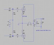
This is simple CCS with BJTs for 6N6p circuit.
Gain is little higher then with common R load.
And it is approximately the same value then load with L (choke)
No 5th harmonic, and little bit lower noise floor. Amount of current
is changing bt R I set and it is good to be the higher value for the start. for example 100 ohm. This is to be established in real circuit with real elements.
C from b-c is for cut the bandwidth from the upper side and it is optional.
Heat sink atached to MJE350...😀
.
🙂
Attachments
Help on this
Hi Zoran/all,
Have you actually constructed this. Iam keen to build a tube pre-amp. Do let me know how this sounded.
Do you have a circuit for the power supply and voltages at the various points in the circuit for testing?
Iam looking at a powersupply at http://www.gyraf.dk/gy_pd/g9/g9_sch.gif
Regards
Vinod
sch from #24 will work , even if I'll check some resistor values (LED models can be somewhat tricky regarding real life - I would use 5mm diffuse green ones , where you can expect 1V93 at 3-5mA through them )
regarding TL783 based series reg ...... I don't like it
use any of HV shunt regs around , Salas made some , for my knowledge
regarding TL783 based series reg ...... I don't like it
use any of HV shunt regs around , Salas made some , for my knowledge
This is simple CCS with BJTs for 6N6p circuit.
Gain is little higher then with common R load.
And it is approximately the same value then load with L (choke)
No 5th harmonic, and little bit lower noise floor. Amount of current
is changing bt R I set and it is good to be the higher value for the start. for example 100 ohm. This is to be established in real circuit with real elements.
C from b-c is for cut the bandwidth from the upper side and it is optional.
Heat sink atached to MJE350...😀
.
🙂
I built a similiar 6n6 for a cheap passive I/V+tube PCM63k analog stage a few years ago, it outperformed the D1jfet it replaced sonically and was even close on 2H. Its a good tube but I get about 10 to 20db less thd with the 5842 and have saved the 6n6p for possibly a P-P circuit, they seem more geared toward P-P to knock down some of the 2H softness. I picked the less than optimal operating point simply to avoid a bypass cap.
Alex Cavalia put together a very nice sounding futterman inspired headamp/preamp with the 6n6p, the Bijou, that would be an interesting simulation (its weakness is also the operating point -cathode bias limiting the output.) I think a better cathode biasing mechanism and powersupply it could be a real firecracker.
I am going to produce a pcb for a driver of two 6n6p tubes in parallel push pull.
If anyone is interested, this will be ultra nice sounding, the pcb unique!
If anyone is interested, this will be ultra nice sounding, the pcb unique!
My idea is to release a PCB + parts list for push pull amp using 6n6p output tubes. Only the driver/input tube 6SL7 will be in the PCB. This way a person can easily build a decent amplifier based on 6n6p.
I posted this circuit a few years ago on how to make a DAC output cathode follower with 6n6p instead of using opamps, and also it can be used to power headphones and can be doubled to lower output impedance.
Important Parts : Hammond 369EX, Choke Hammond 181R 20H, EZ81, 6n6p,
Specifications : tube bias 8.8 ma on 1/2 6n6p, grid current 0.0005ma 1/2 6n6p
Grid bias resistors : grid-HT : 355k, Grid-Ground : 145k.
Power rating : 0.1W , 300R Headphones recommended.

Important Parts : Hammond 369EX, Choke Hammond 181R 20H, EZ81, 6n6p,
Specifications : tube bias 8.8 ma on 1/2 6n6p, grid current 0.0005ma 1/2 6n6p
Grid bias resistors : grid-HT : 355k, Grid-Ground : 145k.
Power rating : 0.1W , 300R Headphones recommended.
Would it be more intelligent to design a driver stage that can be used for any/many sort of output tubes ?
Which features you concentrated on when designed only for 6N6P ?
Can you provide main test results ?
Which features you concentrated on when designed only for 6N6P ?
Can you provide main test results ?
Salutations artosalo,
There is many good driver boards available already so I don't see the point of doing a copy of a copy.
You are right though the driver stage can drive many sort of power tubes but is 'tailored' for the easy to drive triode like 6n6p which has a lot of gain, low input C, Gk is good too, and low grid current. I don't think you would like to drive anything else, except maybe the ECC99 but it is more $$$ than the 6n6p.
I concentrate more on feature such as easy requirements. I didn't do specific driver stage distortion tests because it performed very well, it is simply a common cathode followed with a concertina, a feedback loop, possibility to use cathode or grid bias with parts substitution.
I can provide some tests results later but I don't think it would help anyone, we are talking about a low power amp of which I hope diy users can extract all the advantages versus a typical pentode amplifier. I call it a step in between SET and class AB.
Hi Gabdx!
greets:
Tyimo
Yes, I understand it, but I am interested about your 6N6P parallel PP amp output stage's details. Could you show a schematic, please? is it the Le Barbare amp?My idea is to release a PCB + parts list for push pull amp using 6n6p output tubes. Only the driver/input tube 6SL7 will be in the PCB. This way a person can easily build a decent amplifier based on 6n6p
greets:
Tyimo
...I am interested about your 6N6P parallel PP amp output stage's details...
There are really not many alternatives how to do this sort of output stage.
Below is a fixed bias version with single 6N6P tube.
With two parallel tubes the OPT should be 5k.
Some 11 Vrms of drive voltage is required for full power, which is about 10 W.
If you prefer autobias circuit use some 600 ohms (bypassed) cathode resistor/two triodes and some 320 V as +Ub.
The OPT is same as with fixed bias.
Attachments
Last edited:
Autobias is easier to accomplish and does not require bias adjustments after tube change.
But fixed bias is maybe more linear and provide a bit more power with better efficiency.
But fixed bias is maybe more linear and provide a bit more power with better efficiency.
- Home
- Amplifiers
- Tubes / Valves
- 6N6P tube - focus on