Version 4
SHEET 1 880 680
WIRE 16 -240 -240 -240
WIRE 416 -240 16 -240
WIRE 480 -240 416 -240
WIRE 656 -240 560 -240
WIRE 416 -224 416 -240
WIRE 16 -176 16 -240
WIRE -240 -160 -240 -176
WIRE 656 -160 656 -240
WIRE 416 -144 256 -144
WIRE -96 -128 -176 -128
WIRE -32 -128 -96 -128
WIRE 416 -128 416 -144
WIRE -176 -80 -176 -128
WIRE 144 -80 96 -80
WIRE 368 -80 224 -80
WIRE -16 -48 -16 -80
WIRE 656 -48 656 -80
WIRE 384 -16 384 -32
WIRE 384 -16 144 -16
WIRE 144 0 144 -16
WIRE -16 48 -16 32
WIRE 96 48 96 -80
WIRE 96 48 -16 48
WIRE -96 64 -96 -128
WIRE -16 64 -16 48
WIRE -16 64 -96 64
WIRE 256 80 256 -144
WIRE 384 128 384 -16
WIRE 512 128 384 128
WIRE 672 128 512 128
WIRE 768 128 736 128
WIRE 144 160 144 144
WIRE 144 160 -96 160
WIRE -16 176 -16 64
WIRE 384 176 384 128
WIRE 768 176 768 128
WIRE -208 224 -272 224
WIRE -96 224 -96 160
WIRE -96 224 -128 224
WIRE -64 224 -96 224
WIRE 256 224 256 144
WIRE 336 224 256 224
WIRE -272 288 -272 224
WIRE 256 288 256 224
WIRE 768 288 768 256
WIRE -48 304 -48 272
WIRE 352 304 352 272
WIRE -272 416 -272 368
WIRE -48 416 -48 384
WIRE 256 416 256 368
WIRE 352 416 352 384
FLAG 352 416 0
FLAG -240 -160 0
FLAG 656 -48 0
FLAG 256 416 0
FLAG -48 416 0
FLAG -272 416 0
FLAG -176 0 0
FLAG 512 208 0
FLAG 768 288 0
DATAFLAG 384 16 ""
DATAFLAG 400 -240 ""
DATAFLAG 352 -144 ""
DATAFLAG -96 64 ""
DATAFLAG -48 288 ""
DATAFLAG 352 288 ""
SYMBOL Misc\\triode 384 224 R0
SYMATTR InstName U1
SYMATTR Value 6N6P_AN
SYMBOL res 336 288 R0
SYMATTR InstName R1
SYMATTR Value 82
SYMBOL Misc\\triode 416 -80 R0
SYMATTR InstName U2
SYMATTR Value 6N6P_AN
SYMBOL res 576 -256 R90
WINDOW 0 0 56 VBottom 2
WINDOW 3 32 56 VTop 2
SYMATTR InstName R3
SYMATTR Value 620
SYMBOL res 240 -96 R90
WINDOW 0 0 56 VBottom 2
WINDOW 3 32 56 VTop 2
SYMATTR InstName R4
SYMATTR Value 300
SYMBOL cap -256 -240 R0
SYMATTR InstName C1
SYMATTR Value 220µ
SYMBOL voltage 656 -176 R0
WINDOW 123 0 0 Left 0
WINDOW 39 0 0 Left 0
SYMATTR InstName V1
SYMATTR Value 280
SYMBOL Misc\\triode -16 224 R0
SYMATTR InstName U3
SYMATTR Value 5751
SYMBOL res -64 288 R0
SYMATTR InstName R5
SYMATTR Value 1000
SYMBOL res -32 -64 R0
SYMATTR InstName R6
SYMATTR Value 1200
SYMBOL Misc\\triode 16 -128 R0
SYMATTR InstName U4
SYMATTR Value 5751
SYMBOL voltage -272 272 R0
WINDOW 123 0 0 Left 0
WINDOW 39 0 0 Left 0
SYMATTR InstName V2
SYMATTR Value SINE(0 1.5 1000)
SYMBOL res -112 208 R90
WINDOW 0 0 56 VBottom 2
WINDOW 3 32 56 VTop 2
SYMATTR InstName R7
SYMATTR Value 100k
SYMBOL res 496 112 R0
SYMATTR InstName R9
SYMATTR Value 10000k
SYMBOL cap 672 112 M90
WINDOW 0 0 32 VBottom 2
WINDOW 3 32 32 VTop 2
SYMATTR InstName C2
SYMATTR Value 470µ
SYMBOL res 752 160 R0
SYMATTR InstName R8
SYMATTR Value 300
SYMBOL res -192 -96 R0
SYMATTR InstName R10
SYMATTR Value 10000k
SYMBOL cap 128 0 R0
SYMATTR InstName C3
SYMATTR Value 470n
SYMBOL res 128 48 R0
SYMATTR InstName R11
SYMATTR Value 390k
SYMBOL res 240 272 R0
SYMATTR InstName R12
SYMATTR Value 220k
SYMBOL cap 240 80 R0
SYMATTR InstName C4
SYMATTR Value 470n
SYMBOL res 400 -240 R0
SYMATTR InstName R2
SYMATTR Value 330
TEXT 544 152 Left 2 !.lib tube.lib
TEXT -304 440 Left 2 !.tran 0 20m 0 1u
Would you mind running those FFTs with this .tran and .four argument? (This is what I use to guesstimate THD)
The reason I ask is that I'm getting very different results when I load your circuit into LTspice. The last one shows it just barely able to manage 1V rms into a 32 ohm load, and that at 1% THD with H3 and H5 higher in level than H2 and H4.Code:.tran 0 100m 60m 1u .four 1k 10 v(out) .options plotwinsize=0 .OPTIONS numdgt=8 .option noopiter
--
PS - I'm using Adrian Immler's new models for 6N6P, 6N2P, 12AX7, and 12AT7. They're in the LTspice models thread, which is a sticky up top in this Tubes/Valves forum.
--
Well I am very interested how I can incorporate those code lines in a LTspice circuit simulation. Using .op and then copy paste those lines?
And that Adrian Immler's new models for 6N6P, where can I find this?
Thanks in advance!
I feel like a luddite now...
The graphs of FFT mean FA to me because nobody has taught me how to interpret them.
Could you replace the 12AX7 with 6F12P? Use the triode as the bottom and the pentode strapped as triode for the top? (If there's a model - I dunno if there is but what a tube!)
The graphs of FFT mean FA to me because nobody has taught me how to interpret them.
Could you replace the 12AX7 with 6F12P? Use the triode as the bottom and the pentode strapped as triode for the top? (If there's a model - I dunno if there is but what a tube!)
I use 470R 🙂 Even better probably! Newbie question: Why is the baseline on a downward slope? Just better PSRR at HF or?
Well I am very interested how I can incorporate those code lines in a LTspice circuit simulation. Using .op and then copy paste those lines?
When in your schematic, press the 's' key on your keyboard.
That will bring up the 'Enter text into your schematic' dialog.
Set the radio button to 'SPICE directive'.
Copy and paste the text into the empty field.
Click [OK].
Click 'Run' to run the simulation.
And that Adrian Immler's new models for 6N6P, where can I find this?
Thanks in advance!
https://www.diyaudio.com/forums/search.php?searchid=24560511
When in your schematic, press the 's' key on your keyboard.
That will bring up the 'Enter text into your schematic' dialog.
Set the radio button to 'SPICE directive'.
Copy and paste the text into the empty field.
Click [OK].
Click 'Run' to run the simulation.
https://www.diyaudio.com/forums/search.php?searchid=24560511
Thank you very much rongon!
I feel like a luddite now...
The graphs of FFT mean FA to me because nobody has taught me how to interpret them.
Don't worry. For some reason I haven't been able to master a PCB layout app properly. I'm still relying on the kindness of strangers for PCBs. Silly.
The FFT shows the fundamental tone, and then whatever harmonics are generated at frequencies above that.
In this example, the fundamental is 1kHz, which is the big spike at 1kHz.
The second biggest spike is at 2kHz, which means that's the second harmonic (at double the fundamental frequency).
The third biggest spike is at 3kHz, so you guessed it, it's the third harmonic (H3). As you an see, it's well down from the second harmonic (H2), which means it will sound nice. 🙂
Could you replace the 12AX7 with 6F12P? Use the triode as the bottom and the pentode strapped as triode for the top? (If there's a model - I dunno if there is but what a tube!)
I can try that. I'll get back to you on that.
My suspicion is that it will be impossible to get the grid bias enough above 1V without raising the B+ voltage, or running the poor tube at a really low plate current. If I have to take it down to like 2mA, would that be OK?
--
Hey Rongon! If I can figure out EasyEDA, you can, too!
6F12P - boost B+ to 600V. Give it it's own 10k/47u filter. It works for my phase splitter (different circuit but same abuse of V-hk) 😀
6F12P - boost B+ to 600V. Give it it's own 10k/47u filter. It works for my phase splitter (different circuit but same abuse of V-hk) 😀
I just finished importing the .asc file baudouin0 posted earlier.
The output stage is completely bada$$!!!
The problem I'm having is that I can't replicate the same super-low H3 levels using Adrian Immler's 6N2P model that baudouin0 gets using the Ayumi 5751 model. And, since the 5751 is now a super-collectible, valuable tube, I'd rather see it working with a 6N2P, or even a plain-jane 12AX7. Or a 12AT7. Anything cheap.
When I substitute the 6N2P, I can only get it to bias up with about 130V on its plate, 0.62mA plate current, using 1.5k Rk for a grid bias of -0.93V. That works, close enough, I guess. Be that as it may, the simulation numbers are still really freakin' good.
With a 300 ohm load:
Gain = 3.5X (about 10dB)
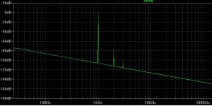
At 2V rms out, THD is 0.0016% (!!!). There's definitely some cancellation going on in there.
The FFT shows 2nd harmonic completely cancelled out, and 3rd harmonic at -95dB, and that is all
That shows that the WCF has been tuned to true push-pull operation into a 300 ohm load, cancelling all H2.
How about into 32 ohms?:
Gain = 3.14X (10dB)
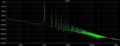
At 1V rms out (which would be enough to drive practically any set of 32 ohm cans into deaf-ray territory), THD is 0.26% (a lot higher).
The FFT doesn't look as good. It shows some cancellation of H2, but lots of higher order harmonics as the amp approaches clipping. I've attached the screenshot of the FFT at 1V rms out into 32 ohms. This is with the 6N2P in place of the 5751.
If a pair of 32-ohm headphones has sensitivity of 100dB SPL at 1mW input, then 1V rms drive would be 15.6mW, which should drive the headphone to put out 112dB SPL. Fer cryin' out loud, ya need more than that???
I guess if you have a low sensitivity pair of headphones like the Fostex T50RP (94dB for 1mW input) then you would need the extra voltage swing into a low impedance load. The T50RP has a 60 ohm impedance. 1V rms out would be 8.3mW. That means 1V will only drive the headphones to 103dB. The max power handling of the T50RP is specified as 1W. Well, I don't think a WCF is going to drive those. But a pair of Audio Technica ATH-M50X? Heck yeah.
Anyway...
--
The output stage is completely bada$$!!!
The problem I'm having is that I can't replicate the same super-low H3 levels using Adrian Immler's 6N2P model that baudouin0 gets using the Ayumi 5751 model. And, since the 5751 is now a super-collectible, valuable tube, I'd rather see it working with a 6N2P, or even a plain-jane 12AX7. Or a 12AT7. Anything cheap.
When I substitute the 6N2P, I can only get it to bias up with about 130V on its plate, 0.62mA plate current, using 1.5k Rk for a grid bias of -0.93V. That works, close enough, I guess. Be that as it may, the simulation numbers are still really freakin' good.
With a 300 ohm load:
Gain = 3.5X (about 10dB)
At 2V rms out, THD is 0.0016% (!!!). There's definitely some cancellation going on in there.
The FFT shows 2nd harmonic completely cancelled out, and 3rd harmonic at -95dB, and that is all
That shows that the WCF has been tuned to true push-pull operation into a 300 ohm load, cancelling all H2.
How about into 32 ohms?:
Gain = 3.14X (10dB)
At 1V rms out (which would be enough to drive practically any set of 32 ohm cans into deaf-ray territory), THD is 0.26% (a lot higher).
The FFT doesn't look as good. It shows some cancellation of H2, but lots of higher order harmonics as the amp approaches clipping. I've attached the screenshot of the FFT at 1V rms out into 32 ohms. This is with the 6N2P in place of the 5751.
If a pair of 32-ohm headphones has sensitivity of 100dB SPL at 1mW input, then 1V rms drive would be 15.6mW, which should drive the headphone to put out 112dB SPL. Fer cryin' out loud, ya need more than that???
I guess if you have a low sensitivity pair of headphones like the Fostex T50RP (94dB for 1mW input) then you would need the extra voltage swing into a low impedance load. The T50RP has a 60 ohm impedance. 1V rms out would be 8.3mW. That means 1V will only drive the headphones to 103dB. The max power handling of the T50RP is specified as 1W. Well, I don't think a WCF is going to drive those. But a pair of Audio Technica ATH-M50X? Heck yeah.
Anyway...
--
Attachments

Last edited:
It is tricky to drive 32R from a few K's. Its never going to be efficient. I think I would be using an audio transformer maybe:
https://uk.farnell.com/oep-oxford-e...2a3e/transformer-1-1-6-45-6-45-150/dp/1172344
But probably from a LTP.
https://uk.farnell.com/oep-oxford-e...2a3e/transformer-1-1-6-45-6-45-150/dp/1172344
But probably from a LTP.
Last edited:
*
* Generic triode model: 6N6P
* Copyright 2003--2008 by Ayumi Nakabayashi, All rights reserved.
* Version 3.10, Generated on Wed Mar 8 12:22:20 2017
* Plate
* | Grid
* | | Cathode
* | | |
.SUBCKT 6N6P_AN A G K
BGG GG 0 V=V(G,K)+-0.25601741
BM1 M1 0 V=(0.021339633*(URAMP(V(A,K))+1e-10))**-0.6377381
BM2 M2 0 V=(0.70167622*(URAMP(V(GG)+URAMP(V(A,K))/13.979799)+1e-10))**2.1377381
BP P 0 V=0.0037683642*(URAMP(V(GG)+URAMP(V(A,K))/19.923433)+1e-10)**1.5
BIK IK 0 V=U(V(GG))*V(P)+(1-U(V(GG)))*0.002184066*V(M1)*V(M2)
BIG IG 0 V=0.0018841821*URAMP(V(G,K))**1.5*(URAMP(V(G,K))/(URAMP(V(A,K))+URAMP(V(G,K)))*1.2+0.4)
BIAK A K I=URAMP(V(IK,IG)-URAMP(V(IK,IG)-(0.0021714264*URAMP(V(A,K))**1.5)))+1e-10*V(A,K)
BIGK G K I=V(IG)
* CAPS
CGA G A 4.2p ; 0.7p added (3.5p)
CGK G K 5.1p ; 0.7p added (4.4p)
CAK A K 1.9p ; 0.2p added (1.7p)
.ENDS
*
* Generic triode model: 5751
* Copyright 2003--2008 by Ayumi Nakabayashi, All rights reserved.
* Version 3.10, Generated on Sat Mar 8 22:42:03 2008
* Plate
* | Grid
* | | Cathode
* | | |
.SUBCKT 5751 A G K
BGG GG 0 V=V(G,K)+0.5559861
BM1 M1 0 V=(0.0052861104*(URAMP(V(A,K))+1e-10))**-0.6766372
BM2 M2 0 V=(0.68913644*(URAMP(V(GG)+URAMP(V(A,K))/58.807619)+1e-10))**2.1766372
BP P 0 V=0.0013669039*(URAMP(V(GG)+URAMP(V(A,K))/85.335234)+1e-10)**1.5
BIK IK 0 V=U(V(GG))*V(P)+(1-U(V(GG)))*0.00079762831*V(M1)*V(M2)
BIG IG 0 V=0.00068345195*URAMP(V(G,K))**1.5*(URAMP(V(G,K))/(URAMP(V(A,K))+URAMP(V(G,K)))*1.2+0.4)
BIAK A K I=URAMP(V(IK,IG)-URAMP(V(IK,IG)-(0.00070754928*URAMP(V(A,K))**1.5)))+1e-10*V(A,K)
BIGK G K I=V(IG)
* CAPS
CGA G A 1.4p
CGK G K 1.4p
CAK A K 0.5p
.ENDS
Thanks. I use those too. The Ayumi models are good, and I'm getting similar results with those or the AI models. They're both good. The AI models simulate grid current and other effects better.
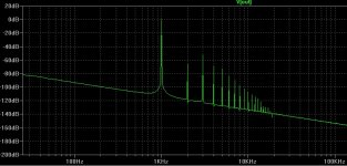
OK, the baudouin0 5751-6N6P WCF circuit using the Ayumi 5751 and 6N6P models, with 1V rms output into a 32 ohm load.
Gain = 3X
1V out into 32 ohms = 0.44% THD (H2 and H3 about equal, but lots of higher order harmonics too, showing that the amp is close to clipping)
Three FFTs are attached.
- The first one is the circuit with 5751, driving a 32 ohm load with 1V rms out. (31mW)
- The second one is the circuit with 6N2P, driving a 32 ohm load with 1V rms out. (31mW)
- The third one is the circuit with 5751, driving a 300 ohm load with 2V rms out. (13.3mW)
Attachments

Last edited:
Would be good to check with the original no FB no WCF circuit too to check we have gone forward.
The original circuit has much higher THD. With a 6N3P and the 6N6P non-WCF, no-NFB circuit there's 0.39% THD with 1V rms into 300 ohms (3.3mW).
So even if you don't trust LTspice simulations of THD, comparing like to like you can see that one will produce more distortion than the other, even if you don't know exactly how much distortion.
So even if you don't trust LTspice simulations of THD, comparing like to like you can see that one will produce more distortion than the other, even if you don't know exactly how much distortion.
It may be worth bypassing the first cathode resistor to get more open loop gain. The only other thing I can think of is throwing more current at the output doubling up the 6n6p or something a little bigger.
- Home
- Amplifiers
- Tubes / Valves
- 6N3/6N6 headphone amp using PCB.