I am going to build this last one,will order resistors an caps.Unless you come up with a new variant............?
What are the 10000K resistors for are they neded?
What are the 10000K resistors for are they neded?
Looks pretty neat - I'll add the components to the PCB. I'm going to see if I can make the FB and WCF modes switchable, too. Would be need to be able to choose push pull or SE.
View attachment 945348
View attachment 945349
With and without WCF. Gain goes up clipping level goes up, distortion goes down. Possible to drive 32R headphones with this. The HT hum actually get a bit better. Some good stuff in there.
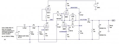
I'm afraid I see a problem. The 5751 looks like it's biased far into grid current territory. 5751 is similar to a 12AX7 but with slightly lower gain. It has high rp of around 50k ohms or so. It works with around 1mA of Ip. That means the 100 ohm cathode resistor is way too small a value for this tube.
LTspice might show good results with something like 0.3V on the 5751 cathode, but I don't think it will work like that in real life.
I replaced the 5751 with a 12AT7, with Rk of 560 ohms for the top and bottom 12AT7s. The 12AT7 cathodes are 1.35V above the grids (still kinda iffy), with Ip of 2.9mA (which is about right for a 12AT7).
The tricky part is biasing the 6N6P to keep it within the max plate dissipation of 4W per triode.
It might be better to use a lower B+ of maybe 225V and a 6DJ8 for the totem pole stage. (6DJ8 max plate voltage is about 125V, so back off to 112.5V to keep it safe.) That actually snaps into place better. Try this:
- B+ = 225V (after the RC decoupling, so maybe 240V raw supply)
- 6DJ8 for input stage with 330R cathode resistors
- 6N6P WCF with current sense resistor of 220R and cathode resistor of 100R
The 6DJ8 biases up at Ip = 8mA, bias is -2.7V
The 6N6P biases up at Ip = 25.5mA, bias is about -1.5V (kind of low)
What do you think?
--
I'm setting it up for 6N2P, 1k cathode resistors.
As far as keeping the 6N6P within 8W, I'm willing to push that to 10W at least... The only Soviet tube I saw not like exceeding it's limits was 6P3S.
As far as keeping the 6N6P within 8W, I'm willing to push that to 10W at least... The only Soviet tube I saw not like exceeding it's limits was 6P3S.
Last edited:
Cathode U3 300mV too low. There is positive grid current entering U2. Post an updated schematic if you want another sim.
Last edited:
.png")
.png")
In simulation, with a 260V B+ and 1k cathode resistors, the 6N2P draws 0.8mA, so the grid bias is -0.8V. That's probably OK, but it does make me worry about grid current effects.
It will be interesting to see if you get the same result in real life. Keep us posted....
In the meantime, I came up with this (attached schematic). It's optimized for a 300 ohm load, but should drive a 50 ohm load well enough to get by. Gain is about 6.8X, according to the sim. It would probably be a little lower IRL.
PS - Remember that if you optimize a WCF for a 32 ohm load, it will have much higher distortion into a 300 ohm load. If you optimize the WCF for 300 ohms, it will have trouble driving a 32 ohm load. A compromise setting will need to be found that's not too bad into 32 ohms or 300 ohms (and will probably be optimized for something like a 100 ohm load).
PPS:
R7 is a build out resistor to inhibit the cathode follower from oscillating into a capacitative load. L1 across R7 bypasses it for audio frequencies, so maintains as low output impedance as possible.
D4 protects the voltage at the cathode of U3 from getting too far from the heater voltage at power up, so that the cathodes don't get 'poisoned'.
D3 is a zener that keeps the grid to cathode voltage of U4 from going to far into cutoff on clipping, which makes the clipping behavior more gentle. Probably helpful in a feedback amplifier.
D1 and D2 clamp the output voltage to no more than about +/-15V, so that downstream solid-state circuits don't get blasted to smithereens (in case you want to use this circuit as a line stage, or if you're worried about your headphones).
--
Attachments
Last edited:
Keep in mind, the feedback forced the voltage swing down - 1V in won't be 1V at the grid, right?
It also looks like lower first cathode resistors make a cleaner higher output.
Can I ask baudouin0 why the first tubes cathode resistors are dissimilar?
It also looks like lower first cathode resistors make a cleaner higher output.
Can I ask baudouin0 why the first tubes cathode resistors are dissimilar?
Yep. Just found that the clipping was slightly more symmetrical if the output DC volts was just a bit lower than half rail. Yep the lower cathode resistors help on the onset of clipping for the output upper 6N6P starts to draw grid current but its only a marginal thing. Simulation seems to indicate if you optimize for a 32R load then it just laughs at a 300R load.
Last edited:
I think you will be surprised at how accurate the models are. I've been building a VHF tuner and even the oscillator and mixer works on LTspice.
Symmetrical clipping means odd order harmonics (asymmetrical clipping indicates the presence of more even harmonics).
Since push-pull operation cancels even harmonics, when you get to the point where you see symmetrical clipping, you've found the push-pull null point. However, if you change the load by very much, you'll see the spectrum of harmonics change along with it.
Basically, if you adjust the circuit for symmetrical clipping with a 50 ohm load, you'll want to switch the load to 300 ohms and see what the distortion products look like with that. What I've found is that a WCF optimized for 50 ohms will make quite high amounts of THD into a 300 ohm load, even though it will easily drive that higher load with a lot of volts before clipping.
Of course, with a 300 ohm load, does it matter if you get 1V rms out with 0.1% THD vs. 0.01%? I don't know. (1V rms into a 300 ohm load = 3.3mW rms)
Last edited:
Keep in mind, the feedback forced the voltage swing down - 1V in won't be 1V at the grid, right?
Right, but there is the problem of contact potential. There might be quiescent grid current to contend with, which will vary between tube samples (depending on whether or not they're gassy at all).
.png")
.png")
Would you mind running those FFTs with this .tran and .four argument? (This is what I use to guesstimate THD)
The reason I ask is that I'm getting very different results when I load your circuit into LTspice. The last one shows it just barely able to manage 1V rms into a 32 ohm load, and that at 1% THD with H3 and H5 higher in level than H2 and H4.
--
PS - I'm using Adrian Immler's new models for 6N6P, 6N2P, 12AX7, and 12AT7. They're in the LTspice models thread, which is a sticky up top in this Tubes/Valves forum.
--
Code:
.tran 0 100m 60m 1u
.four 1k 10 v(out)
.options plotwinsize=0
.OPTIONS numdgt=8
.option noopiter
The reason I ask is that I'm getting very different results when I load your circuit into LTspice. The last one shows it just barely able to manage 1V rms into a 32 ohm load, and that at 1% THD with H3 and H5 higher in level than H2 and H4.
--
PS - I'm using Adrian Immler's new models for 6N6P, 6N2P, 12AX7, and 12AT7. They're in the LTspice models thread, which is a sticky up top in this Tubes/Valves forum.
--
Last edited:
- Home
- Amplifiers
- Tubes / Valves
- 6N3/6N6 headphone amp using PCB.