Just got through this whole thread and very informative especially regarding the mosfets.
Planning to incorporate these into one of my current projects.
Thanks guys.
Nice work.
Planning to incorporate these into one of my current projects.
Thanks guys.
Nice work.
I believe the important parameter is a low reverse transfer capacitance and enough drain source voltage capacity. Not sure how the IRF310 compares to the others...
Mosfets IRF 710/820/821 will be fine for this application? I've got 310, maybe a bit small.
I've been using IRF820s for at least 20 years in that application with no problems. If the reverse transfer capacitance is an issue (and with 6SN7s ahead of it, it hasn't been for me), you could cascode. But a plain-Jane IRF820 source follower is sufficient to drive the hell out of the grids- or in screen drive with higher perveance tubes like 6JN6, 6LF6, and their ilk. And they're dirt cheap.
One thing to note- the source followers don't have to run Class A. That can save you some thermal issues.
310:
transfer capacitance: 6.3 pf
gate voltage 400v
gs voltage: 20v
820:
transfer capacitance: 37 pf
gate voltage 500v
gs voltage: 20v
Am I looking for a higher transfer capacitance?
transfer capacitance: 6.3 pf
gate voltage 400v
gs voltage: 20v
820:
transfer capacitance: 37 pf
gate voltage 500v
gs voltage: 20v
Am I looking for a higher transfer capacitance?
As Chris and I both found out, either choose a mosfet that has zener diodes internally from gate to source, or add them externally. Turn on - warm up transients will blow the gate out of an unprotected mosfet.
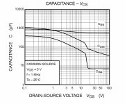
Look for a spec called Crss. You want it to be low, preferably under 10 pF, and constant under the range of voltages that will be seen in actual use. There is uaually a graph of this and other capacitance related specs VS voltage. Most fets are quite non linear below a certain voltage, then go fairly constant. The transition voltage is usually 10 to 50 volts although some fets never flatten out.
This means that you are putting a capacitor that changes value with the applied signal voltage directly in the audio path. TIM and PIM distortions can result, so we want to keep the capacitance constant and low.
I believe the important parameter is a low reverse transfer capacitance
Look for a spec called Crss. You want it to be low, preferably under 10 pF, and constant under the range of voltages that will be seen in actual use. There is uaually a graph of this and other capacitance related specs VS voltage. Most fets are quite non linear below a certain voltage, then go fairly constant. The transition voltage is usually 10 to 50 volts although some fets never flatten out.
This means that you are putting a capacitor that changes value with the applied signal voltage directly in the audio path. TIM and PIM distortions can result, so we want to keep the capacitance constant and low.
Look for a spec called Crss. You want it to be low, preferably under 10 pF,
thxs tubelab.
Yes I get it now.
So the 310 are more ideal as they only have a Crss of 6.3 pf.
I see that some have put 2 x 15v zeners back to back to avoid over voltages and smoked fets.
This is a good practice with the 310 also? These look identical, just slightly different voltage and capacitance values.
I've been using IRF820s for at least 20 years in that application with no problems.
I used that one for a while. It needs external diodes, and yes I have blown a few because they were not present.
I have used Toshiba parts for the last 5 years. Look at the Toshiba 2SK3563. It has protection diodes built in, and the Crss is ruler flat above 20 volts. The case is isolated so that the heat sink will not shock you.
I found an IRFR310, but not an IRF310.
Crss 6.3pF VDS=25V, f=1.0MHz
IRFR310 looks good above 30V for Crss flatening out.
MTD2N40/MTD1N50 are the only FETs so far that I have found data at high VDS values and it shows a change in Crss from 7pF to 3pF with a VDS change from 35V to 300V for the MTD2N40, and 7pF to 2.5pF for a VDS change from 25V to 500V for the MTD1N50.
IRFR310 looks good above 30V for Crss flatening out.
It looks good, but hard to tell on the scale used. Look at this one.
Attachments
I've got 4 handy I bought last time I was in USA.
So as long as the V+/V- on drain-source is at least 30 volts it looks good.
Keeping it around 5mA?
and 2 zeners back to back.
So as long as the V+/V- on drain-source is at least 30 volts it looks good.
Keeping it around 5mA?
and 2 zeners back to back.
820:
transfer capacitance: 37 pf
More like about 8-10pF, and very constant for Vds > 20. FWIW, I have never blown one up used in this service, nor seen any excessive distortion due to Crss modulation.
ok good to know SY.
Now regarding voltage across the drain and source.
I have some 220/25 volt trannies. Thinking of putting these in reverse in with a 5 volt secondary to get around 60 volts rectified.
Or maybe a voltage doubler, but not sure how much the extra ripple will effect the FET. Had bad experiences with doublers. Don't like them.
60 volts + and - either side of the FET would be enough? I see most use a bit more depending on the voltage swing.
I used 220:110 transformers. These are pretty plentiful and cheap in Asia, not sure about GB though. When working out your voltages, don't forget that the bias voltage will knock some of the available swing from the -ive.
Cheers,
Chris
Cheers,
Chris
Ok min 100v. great.
I can pick up some cheap 220/12v 0r 9v transformers and hook them up in reverse to the 6 v secondaries I have.
They will give me 110-146 AC. from a 6v secondary I have on a big iron.
Yes we have plenty of step down transformers here (Uruguay) also.
220/110 with plenty of power.
I can pick up some cheap 220/12v 0r 9v transformers and hook them up in reverse to the 6 v secondaries I have.
They will give me 110-146 AC. from a 6v secondary I have on a big iron.
Yes we have plenty of step down transformers here (Uruguay) also.
220/110 with plenty of power.
Just picked up a 4 USD 220v/12v 300mA transformer.
In reverse with the 6v heater (5 amps), secondary and i get a nice 115 volts unrectified.
This will be perfect for the mosfet drain and source I assume as it only consumes 5-10 mA.
And maybe also for the fixed bias on the grids of the output tubes.
BUT I got a quote for a transformer with 2 x 110 secondaries @ 1.5 amps each:
100 USD!!!!!!
Too much for a simple EI power tranny. These are intended for 2 floating supplies for a circlotron.
Have to search for some surplus step downs.
I have a question regarding fixed bias.
I see some designs with individual fixed bias on each split signal.
Others I have seen fixed bias connected in the middle a matched resistor either side of the opposite rails.
In what situations do you use individually controlled fixed bias and just 1 bias control in the mid point between rails?
I see some designs with individual fixed bias on each split signal.
Others I have seen fixed bias connected in the middle a matched resistor either side of the opposite rails.
In what situations do you use individually controlled fixed bias and just 1 bias control in the mid point between rails?
If you are fussy about bias, i.e. each tube of each pair biased within a couple/few milliamps, then you would use a pot for each tube. If you are less fussy, or use matched tubes, then the second method, a pot for each pair.
BTW Chris and George and everyone, this has been a fantastic and educational thread, thanks heaps!
BTW Chris and George and everyone, this has been a fantastic and educational thread, thanks heaps!
- Status
- Not open for further replies.
- Home
- Amplifiers
- Tubes / Valves
- 6L6GC AB2 Amp