And there you go! Grid referenced to gnd and not -ve, as is the output node, plate load is gone, and the cathode load is now 4K7.
Works fine, and I really should have a play with some of the others. 🙂
Hi , very nice work. Some of us are not good reading schematics. Can you make some more photos to help us do this modifications ? The caps are 1uf i guess , what values are the resistors ? For the caps, have you drilled the board or are the caps soldered directly on the components around ?
Hi there, I've no particular desire to write a how-to, but i can answer the questions. No drilling, values are in the schematic, the parts all came with the kit (although I'm not saying that they're ideal values as I've not done the work).
That should give you all you need to know about the differences between the two, and thinking through the 'how' is the fun part!
That should give you all you need to know about the differences between the two, and thinking through the 'how' is the fun part!
Before has been suggested to divide in the board the return track of signal (the - ) from the general gnd power supply. It is still suggested or not?
like in this image...
 netteté Cut out.jpg")
other suggested also this....
'99% reduction in hum with just 2 wires and 3 cuts that separate the filament supply ground from audio ground'.

are those modifications still valid?
better sound/silence obtained?
Thank you
like in this image...
other suggested also this....
'99% reduction in hum with just 2 wires and 3 cuts that separate the filament supply ground from audio ground'.
are those modifications still valid?
better sound/silence obtained?
Thank you
And there you go! Grid referenced to gnd and not -ve, as is the output node, plate load is gone, and the cathode load is now 4K7.
Works fine, and I really should have a play with some of the others. 🙂
Interesting! How different is the sound with a cathode follower? Can you try to describe it?
Interesting! How different is the sound with a cathode follower? Can you try to describe it?
I'm interested too!!!
Waiting for description....
Thank you
To be honest, not a huge difference, but my setup currently isn't really tip top.
Tell you what - I should be able to do some measurements on them easily enough and compare the two objectively. I'd intended to anyway, I just haven't done it yet. 🙂
Tell you what - I should be able to do some measurements on them easily enough and compare the two objectively. I'd intended to anyway, I just haven't done it yet. 🙂
why I would be getting unwanted distortion?
The power supply voltage is 28VDC, pretty low.
Last edited:
Is plus and minus 28V so you can think of it as 56V. It is still low and that compounded with an incorrect bias translated to what your got.
Before has been suggested to divide in the board the return track of signal (the - ) from the general gnd power supply. It is still suggested or not?
like in this image...
View attachment 732909
other suggested also this....
'99% reduction in hum with just 2 wires and 3 cuts that separate the filament supply ground from audio ground'.
are those modifications still valid?
better sound/silence obtained?
Thank you
Tried this on mine just now, it made a 10db INCREASE in hum. That said, mine is somewhat modified in that regard, with a bigger cap for the heaters among other things, so YMMV.
Thanks to all for different tipe of upgrading, specially to reduce hum
But is possible to give more volts to reduce the distortion?
The filament is simple to regulate by new resistance or by a lm78xx.
The caps is possible to increase with new at more volts.
Culd be necessary others?
But is possible to give more volts to reduce the distortion?
The filament is simple to regulate by new resistance or by a lm78xx.
The caps is possible to increase with new at more volts.
Culd be necessary others?
I've ordered another board specifically for modding so I'd be interested in upping the voltage as well and getting the most out of the 5654w tubes I've got waiting.
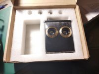
Experimental board arrived!
What sort of voltage would you suggest aiming for? The data sheet seems to suggest up to ~180v
What sort of voltage would you suggest aiming for? The data sheet seems to suggest up to ~180v
twice the voltage for starters, this will need modding the boards for the new voltage...a new psu..
Hi Nuovo
I bought this one in kit form: AC 12V 6J1 Valve Pre-amp Tube PreAmplifier Board Headphone HiFi Amplifier Buffer | eBay
I intend to change out things like the caps for higher voltage and generally butcher the board in pursuit of knowledge. No recommendations or endorsement implied, it really is a toy that costs less than a beer.
They are available from the usual outlets - Ali, eBay, Banggood etc.
Looking at the circuit, we have a voltage multiplier which is fed rectified 12vac which gets us the ~28v (looking at just the upper half).
The 2SD667 is good for 80Vceo so is it just a case of supplying say 18-24vac rectified and upping the voltage ratings of the capacitors to safe levels to get a higher supply voltage, or is there more too if than that?
(Obviously taking care of the 6.3v heater supply separately)
I bought this one in kit form: AC 12V 6J1 Valve Pre-amp Tube PreAmplifier Board Headphone HiFi Amplifier Buffer | eBay
I intend to change out things like the caps for higher voltage and generally butcher the board in pursuit of knowledge. No recommendations or endorsement implied, it really is a toy that costs less than a beer.
They are available from the usual outlets - Ali, eBay, Banggood etc.
twice the voltage for starters, this will need modding the boards for the new voltage...a new psu..
Looking at the circuit, we have a voltage multiplier which is fed rectified 12vac which gets us the ~28v (looking at just the upper half).
The 2SD667 is good for 80Vceo so is it just a case of supplying say 18-24vac rectified and upping the voltage ratings of the capacitors to safe levels to get a higher supply voltage, or is there more too if than that?
(Obviously taking care of the 6.3v heater supply separately)
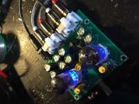
on the same board I use a 14vc and have 35vdc on capacitors (on max limit voltage).
Infact I want change capacitors.
Your ideas to increase voltage its the same mine....But how much is possible increase?
In the same page you can also buy a amplifier in black case and probaly is present a circuit to hi voltage (you can see a toroid....)but how much voltage I don't know...
Infact I want change capacitors.
Your ideas to increase voltage its the same mine....But how much is possible increase?
In the same page you can also buy a amplifier in black case and probaly is present a circuit to hi voltage (you can see a toroid....)but how much voltage I don't know...
- Home
- Amplifiers
- Tubes / Valves
- 6J1 China preamp thoughts