Yes, the sweep tubes always have conservative specs. 10W is the limit for 6EM5 I use, but I tested them with 14W without any red electrodes.Sure, the tube gets more efficient as the B+ and OT primary Z go up. Maybe that will be breaking some B+ voltage specs then instead. The tubes are cheap enough at least. One should really have an 8K Ohm or so OT for playing with these 9 pin tubes.
For audio use, one should be able to match the 6BQ5/EL84 spec of 12 Watts plate diss. Same size plate.
On the other hand, $37 for an Edcor GXPP 15 Watter OT, or $47 for a CXPP 25 Watter OT,
versus $6 to $10 for some bigger tubes.
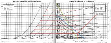
I always found something curious about valves: if the load line hit the knee, we have a screen/G2 grid "spike" current at the time the signal reaches the knee. But if the signal overload the valve, getting an more vertical loadline and out of knee area, the excess peak current g2 disappears. I use my amplifier with PL509 slightly overloaded, and g2 current can never deplete the g2 regulator (which in my case is a simple supply with valve gas regulator, 105A2). If I use a lighter load on the amplifier, the regulator gas valve is off when the g2 attempts to consume the huge current when the anode voltage reaches the knee.Ok , here is the screen current chart for my op 250vdc plate and screen and -5 vdc
So I always recommend to never using an strong/hard G2 regulator; is good to limit peak current with resistors or current limiting.
I suspect most amps fail due to G2 overheat... but we audiophiles never use amps in saturation, so even if load hit the knee we have a long life to our tubes.
Yes, there is definately a tradeoff on the load, but since the speaker's impedance varies all over the place anyway, there are some leaway on where to locate the load line.I suspect most amps fail due to G2 overheat... but we audiophiles never use amps in saturation, so even if load hit the knee we have a long life to our tubes.
For hi-fi, since it is seldom overdriven, higher loads are usually preferred even if that means a bit less output power. But for guitar amps, the designers always aim for the maximum power - it goes to "11" - so a steeper load line is often used, this also helps a bit with the screen voltage - but then again these amps are usually operated well over the Design Center limits anyway, so not sure if it really matters that much.😉
Skal, if you are not making an guitar amp, you can relax about G2. Even so, for curiosity, is good to know the screen consumption and to using graphs...
ok going to strap this up now, should take me an hour or so will be using the 250vdc plate and screen with -5 .
no not guitar amp ,hifi amp , am i in the wrong thread?
got no idea of grid stopper so i will go with 100ohms and 1meg for grid leak cathode at 0vdc
skal
no not guitar amp ,hifi amp , am i in the wrong thread?
got no idea of grid stopper so i will go with 100ohms and 1meg for grid leak cathode at 0vdc
skal
Last edited:
For these high gm tube I go with at least 1k for grid stopper, and I use values like 10k in my projects (reduces the clipping problems).ok going to strap this up now, should take me an hour or so will be using the 250vdc plate and screen with -5 .
no not guitar amp ,hifi amp , am i in the wrong thread?
got no idea of grid stopper so i will go with 100ohms and 1meg for grid leak cathode at 0vdc
skal
For grid leak I use less than the manual recommended for fixed bias. The RCA manual recommends 1M but I prefer to use max. 470k for less shifting trouble, and long service life.
No, you are in correct thread🙂. Our DIYA forum has another section dedicated to guitar enthusiasts.
Ok ,i have breadboard the finals now and the initial current for the plate and screen are off a lot.
plate and screen voltage 250vdc -5 grid bias
plotted plate current 33ma-actual plate current 23.6ma
plotted screen current 7.2 to 10ma -actual screen current 2.6ma
Humm?
is this what you call cold bias
why are the reading this low , wrong AB loadline.
feel free to comment
regards
skal
plate and screen voltage 250vdc -5 grid bias
plotted plate current 33ma-actual plate current 23.6ma
plotted screen current 7.2 to 10ma -actual screen current 2.6ma
Humm?
is this what you call cold bias
why are the reading this low , wrong AB loadline.
feel free to comment
regards
skal
Last edited:
Probably this is because these valves have more spread of characteristics than other normal types, like various members here (jazbo8, smoking-amp, ...) noted.Ok ,i have breadboard the finals now and the initial current for the plate and screen are off a lot.
plate and screen voltage 250vdc -5 grid bias
plotted plate current 33ma-actual plate current 23.6ma
plotted screen current 7.2 to 10ma -actual screen current 2.6ma
Humm?
is this what you call cold bias
why are the reading this low , wrong AB loadline.
feel free to comment
regards
skal
For correcting this I suggest to make the G1 bias adjustable and independent for each output valve (and in some cases people regulate the G2 supply).
hmm , so what should i be looking at ,the current each tube is using something else.
regards
skal
regards
skal
Maybe a little range of adjustment, like -5V to -4V, is sufficient to adjust them to desired bias.
Triode?
skal and all,
This thread is about using 6HB6’s as a push-pull output tube. Looking at the posts they all look to be pentode.
How would this tube operate in triode push pull mode?
smoking-amp are you willing to trace triode curves?
Thanks DT
skal and all,
This thread is about using 6HB6’s as a push-pull output tube. Looking at the posts they all look to be pentode.
How would this tube operate in triode push pull mode?
smoking-amp are you willing to trace triode curves?
Thanks DT
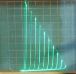
Here are some curves for 6HB6 in Triode and Schade modes.
10 mA/div Vert., 50 V/div Horiz. about 1.5 V/step
This was one of the better 6HB6s for triode mode, some have rather rolled off curves on the HV side. Typical g1/g2 Mu is around 30.
If you look at the gm curves for the 6HB6 (page 5 of datasheet, link: )
http://frank.pocnet.net/sheets/135/6/6HB6.pdf
The section of each gm curve where it straightens out before curving the other way is where the grid 1 has square law V to I. (below that it has higher than 2.0 power law, and above it its less than 2.0 power law)
The grid 2 on the other hand is fairly steady around 1.45 power law.
So using a tube in triode mode locks in feedback through a different power law electrode than what is driving it. They would need to be the same power law for Mu voltage gain to stay constant. You end up with 2nd harmonic distortion and trailing off higher orders. Great if you like old tube radio sound. Class A P-P operation will fix the 2nd harmonic.
Schade feedback on the other hand uses linear feedback, and the resultant curves show that in Spades. It also preserves the max power output of pentode mode, and it can have lower output Z. It does require a more sophisticated driver stage however, performing V to I conversion. The RCA design (linked) is a high performance one. Usually, just a pentode driver gets used for Schade Fdbk. Or even a triode driver with plenty of cathode degeneration.
I no longer consider triode mode to be acceptable for HiFi, except for sound effects. (even with real triodes unless in class A P-P) And UL mode locks in the same distortion, but that's usually in a P-P setup that eliminates some 2nd harmonic. (class AB though, converts the 2nd harmonic to odd harmonics)
Partial Fdbk (versus Schade Fdbk) works even better at linearization. The feedback R's go back to the driver grids or cathodes instead of the driver plates. And doesn't require V to I conversion at the driver plate (easier on the driver).
Attachments
Last edited:
Partial Fdbk (versus Schade Fdbk) works even better at linearization. The feedback R's go back to the driver grids or cathodes instead of the driver plates. And doesn't require V to I conversion at the driver plate (easier on the driver).
Partial feedback?
Didn't hear that name before but I used it some 20y ago in a PP-UL 6550 amp. Resistor from the anode of each 6550 to the cathode of the opposite driver. ECC82 i think, not my favorite type but the amp worked quite well with my simple PA speakers.
"Partial feedback?"
Not sure how universal the term is. But from various DIY discussions I have picked up "Local Feedback" as not including the OT, and being looped around just one stage. Schade setup is an example. UL is another.
(somewhat unclear about CFB really meeting the criteria, since some of that goes through the OT, from plate winding to cathode winding)
And "Partial feedback" meaning not including the OT, could be multi-stage (typically driver and outputs) and the term may be inclusive of Local Feedback.
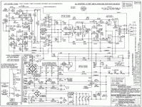
Some examples of Partial Feedback would be the Citation II, ARC D51, Macs, Thorsten Loesch design
(some driver grid isolation caps missing in 2nd schematic I think)
The crossed feedbacks to the driver grids version is also somewhat unclear as to meeting the criteria of staying out of the OT, at least for class aB. (when in class B mode, the signal has to go across the primary halves of the OT)
Not sure how universal the term is. But from various DIY discussions I have picked up "Local Feedback" as not including the OT, and being looped around just one stage. Schade setup is an example. UL is another.
(somewhat unclear about CFB really meeting the criteria, since some of that goes through the OT, from plate winding to cathode winding)
And "Partial feedback" meaning not including the OT, could be multi-stage (typically driver and outputs) and the term may be inclusive of Local Feedback.
Some examples of Partial Feedback would be the Citation II, ARC D51, Macs, Thorsten Loesch design
(some driver grid isolation caps missing in 2nd schematic I think)
The crossed feedbacks to the driver grids version is also somewhat unclear as to meeting the criteria of staying out of the OT, at least for class aB. (when in class B mode, the signal has to go across the primary halves of the OT)
Attachments

Last edited:
some driver grid isolation caps missing in 2nd schematic I think
The circuit will work without caps as drawn. At least mine does. I have a very similar design, except for sand based CCS's in both tails, and sweep tube outputs.
The crossed feedback is great for reducing crossover distortion and high order harmonics provided a decent OPT is used. My $16 guitar amp OPT's like to cause high frequency instability and oscillation if too much crossed feedback is applied.
I think the crossed grid Fdbks maybe requires a better OT than the non-crossed cathode Fdbks. Also, Fdbk to the driver grids looks just like low input Z Schade Fdbk as far as the input stage or splitter sees it. The voltage swing issue is greatly reduced at least. While the cathode feedback version requires more voltage from the front end, but at least it's high Z input.
A differential (CCS tail especially) driver should be especially effective at fixing the crossover distortion, from seeing the whole picture.
The RCA 50 Watt amp Schade driver setup is still a bit of a mystery to me, since it uses both Schade to the driver plates, and Partial Fdbk to the driver cathodes. Seems like the Schade loading on the driver plates greatly reduces the loop gain for the cathode Fdbk loops.
If it were configured so that it was just a gain tradeoff, I could see the Schade portion used for stability reasons. Would probably need modding to a Gyrator load for the driver plates instead of a real R load to avoid wasting gain.
It could also use a more differential tail configuration for crossover fixup. The cathode Fdbk does act doubly to linearize the V to I conversion for the Schade part (beside the straightforward cathode Fdbk). Hard to tell what the tradeoffs are achieving overall. This is something for the Simulator I guess.
Last edited:
late edit:
I forgot to mention that using the differential driver stage also largely eliminates the crossed feedback crossing thru the OT issue, when in class B (output), since both feedbacks affect both tubes equally.
I forgot to mention that using the differential driver stage also largely eliminates the crossed feedback crossing thru the OT issue, when in class B (output), since both feedbacks affect both tubes equally.
- Status
- Not open for further replies.
- Home
- Amplifiers
- Tubes / Valves
- 6HB6 as finals