You need to use more like a 7500 Ohm OT with B+ at 375 V.
Or else drop the B+ to 250 V with the 5K OT.
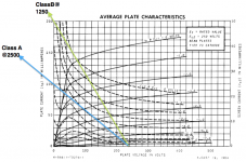
The class B load line goes between B+//0 mA and 0V//(4x B+/Zpri) to get the slope matching the OT primary Z. It then should stay roughly within (below) the max plate dissipation curve. (there is some % time when the tube is cut off, so the average needs to stay below the curve.) So plot some max current points at every 50 V increment and draw the hyperbola through them for the max diss. curve. (max current = (Max Watts)/V)
The class B load curve should also pass through just above the corner in the plate curve for the chosen Vg2. Some adjustment of chosen B+ and Vg2 may be required to meet all the conditions.
Then the class A part of the load line uses half the slope and passes through idle current (for one tube) at V=B+. It also needs to stay within (below) the max diss. curve.
Or else drop the B+ to 250 V with the 5K OT.
The class B load line goes between B+//0 mA and 0V//(4x B+/Zpri) to get the slope matching the OT primary Z. It then should stay roughly within (below) the max plate dissipation curve. (there is some % time when the tube is cut off, so the average needs to stay below the curve.) So plot some max current points at every 50 V increment and draw the hyperbola through them for the max diss. curve. (max current = (Max Watts)/V)
The class B load curve should also pass through just above the corner in the plate curve for the chosen Vg2. Some adjustment of chosen B+ and Vg2 may be required to meet all the conditions.
Then the class A part of the load line uses half the slope and passes through idle current (for one tube) at V=B+. It also needs to stay within (below) the max diss. curve.
Last edited:
Almost there... follow smoking-amp's instructions and refer to the plot on post #10, do you see the class A load line in light blue? You need to shift your class A load line up by the idle current. It is also better to use the Ep-Ip characteristic (Eg1) with a fixed screen voltage instead of the one you are using which shows Eg1=0V at various Eg2's.Ok , here is me trying to do AB load line , please feel free to comment on the loadline.
Class A still needs to be shifted up, even though it is just shown for reference purpose, it is still good to know how it sits on the Ep-Ip characteristic.
Hmmm... with 115R into LM317 legs (like in your schema) your reg will be out of regulation (will regulate to 400+V) and you need to drop with external resistors... if you like to use them, you start with the original value (200R) or maybe use a little more (220-270R, maybe), to obtain desired regulation.My interpretation of how i see it.. on left right side org is a difference
Interesting to see the people here using the load line technique. In the Patrick turner site (for example) are several methods for calculating and using the load line.
ok DIYBras ,got it work for now, had the transistor connected wrong , had to change the 115 ohm to a 220 ohm .
i think i will have to mod it, when i settle on a screen voltage
cheers
skal
i think i will have to mod it, when i settle on a screen voltage
cheers
skal
Last edited:
Not sure what you mean.. what is the bias current set at? Whatever it is, just shift the class A line up, so it passes through (Ep0, Ip0) with a 2.5k slope.jazbo8 the only way i can push the current up is to lower the B+ or am i wrong

This is what I meant, assuming 33mA of bias.
An externally hosted image should be here but it was not working when we last tested it.
Ok , this is baffling that class A 320vdc loadline is no longer @ 2k5 it is more like 2k3 , you
use a different primary load to put the class A portion in the linear area where the knee is correct me if i am wrong .
cheers again
skal
use a different primary load to put the class A portion in the linear area where the knee is correct me if i am wrong .
cheers again
skal
Last edited:
No I did the sketch rather quickly, so the slope looks to be off, in reality, the slope should still be 2.5k, the key is to have the load line pass through 250V and 33mA.Ok , this is baffling that class A 320vdc loadline is no longer @ 2k5 it is more like 2k3 , you
use a different primary load to put the class A portion in the linear area where the knee is correct me if i am wrong .
hmm, i thought the loadline was the op point , this were the confusion set in { laugh}
So, i still do not fully understand your manoeuvre but i am getting their , i know theirs a lot more to understand distortion , clipping and other stuff , i know i learn't a lot over the pass day's.
So, i still do not fully understand your manoeuvre but i am getting their , i know theirs a lot more to understand distortion , clipping and other stuff , i know i learn't a lot over the pass day's.
just for fun i will try to work out the wattge of the finals
P = (HT-Vmin) * Ipeak / 2
P = (250-50) * 0.127 / 2
= 12.7w
P = (HT-Vmin) * Ipeak / 2
P = (250-50) * 0.127 / 2
= 12.7w
Even more interesting to estimate the Watts dissipated in the finals:
Using the transition point from class A to class B: (where the Watt limit hyperbola will be getting close)
165 mA x 70 V => 11.55 Watts (more than the 10 Watt rating)
The tubes are running a bit hot yet. Maybe adjust B+ back to +230 V.
(or scaling from Scott17's known schematic: 8K and 294 V => 5K and Sqrt(5K/8K) x 294V = 232 V) Which will reduce the output power down to around 9 Watts too. But lowers tube diss. to like 140 V x 70 mA = 10 Watts.
So if you want more Watts out, you need to double the tubes up. (can just double the current #s on the left side of the plate curve graph, or instead, double the 5K to 10K OT loading, as seen by a single tube)
OR, use a 6GE5/6JN6/12GT5/12JT6/6JZ6/21HB5..... tube, which is about twice the tube Watts. (although much lower grid 1 gm than 2 6HB5s, ie. will require a lot more drive signal(s))
Last edited:
I thought the earlier posts showed that these little buggers could take quite a bit of abuse, so why not crank it up? Turn up the plate voltage and use as you suggested a higher Ra-a OPT, should be able to do 15W+ no sweat.
Sure, the tube gets more efficient as the B+ and OT primary Z go up. Maybe that will be breaking some B+ voltage specs then instead. The tubes are cheap enough at least. One should really have an 8K Ohm or so OT for playing with these 9 pin tubes.
For audio use, one should be able to match the 6BQ5/EL84 spec of 12 Watts plate diss. Same size plate.
On the other hand, $37 for an Edcor GXPP 15 Watter OT, or $47 for a CXPP 25 Watter OT,
versus $6 to $10 for some bigger tubes.
For audio use, one should be able to match the 6BQ5/EL84 spec of 12 Watts plate diss. Same size plate.
On the other hand, $37 for an Edcor GXPP 15 Watter OT, or $47 for a CXPP 25 Watter OT,
versus $6 to $10 for some bigger tubes.
Last edited:
Hi jazbo8,
what did you mean by this statement.
cheers
skal
what did you mean by this statement.
Class A still needs to be shifted up, even though it is just shown for reference purpose, it is still good to know how it sits on the Ep-Ip characteristic.
cheers
skal
Even more interesting to estimate the Watts dissipated in the finals:
Using the transition point from class A to class B: (where the Watt limit hyperbola will be getting close)
165 mA x 70 V => 11.55 Watts (more than the 10 Watt rating)
The tubes are running a bit hot yet. Maybe adjust B+ back to +230 V.
(or scaling from Scott17's known schematic: 8K and 294 V => 5K and Sqrt(5K/8K) x 294V = 232 V) Which will reduce the output power down to around 9 Watts too. But lowers tube diss. to like 140 V x 70 mA = 10 Watts.
(s))
where is the transition point from class A to class B
No I did the sketch rather quickly, so the slope looks to be off, in reality, the slope should still be 2.5k, the key is to have the load line pass through 250V and 33mA.
that 250v @33ma is this the current draw for two? how do i work out the screen current use at idle and at full signal..
cheers
skal
- Status
- Not open for further replies.
- Home
- Amplifiers
- Tubes / Valves
- 6HB6 as finals