Geez, the place where I got the cheap 6197 tubes on Ebay a few years ago just sky-rocketed their price on them today. Forget about them for a cheap tube option.
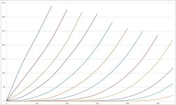
Hello ,can you me explain what is Crazy/Twin drive please ?Here are some plate curve sets for 13GB5. All curves are 50 mA/div Vert. and 50V/div. Horiz.
By the way, 13GB5 is nearly identical to 21HB5 for plate curves. (another $1 tube back when, but 12 pin Compactron)
1) 13GB5 pentode, 130 Vg2, 2 Vsteps on g1
2) 13GB5 triode, 7 Vsteps on g1
3) 13GB5 g2 drive, 110 V max Vg2, 7 Vsteps on g2
4) 13GB5 Crazy/Twin drive, 75V max Vg2, 7 Vsteps on g2
Regards
Crazy drive or twin drive describes a drive method that some members of this forum explored pretty heavily 10 to 12 years ago. It is a technique where both G1 and G2 have signal drive applied to them. This gives a triode like set of curves often with a rather high Mu.
See this old thread for some details. My test schematic is in post #30.
https://www.diyaudio.com/community/threads/g1-g2-mu-scaled-drive-strawman-design.163940/
I have refined this further to what I now call UNSET where G2 is at an AC ground potential (bypassed to ground) and G1 is either at an AC ground or has negative plate to grid feedback applied. The drive signal is applied to the cathode through a transformer or P-mos FET follower. This gives good triode curves, and the Mu can be adjusted by the feedback ratio.

Tubelab: Have you tried decoupling G2 to the cathode instead? It would of course take one Mosfet per channel instead of a common G2 supply but would result in true pentode operation and possible a bit more output power.
I'm probably being Captain Obvious here, but I've read a lot about the UNSET and never seen a reference to this.
Thanks for reply.Crazy drive or twin drive describes a drive method that some members of this forum explored pretty heavily 10 to 12 years ago. It is a technique where both G1 and G2 have signal drive applied to them. This gives a triode like set of curves often with a rather high Mu.
See this old thread for some details. My test schematic is in post #30.
https://www.diyaudio.com/community/threads/g1-g2-mu-scaled-drive-strawman-design.163940/
I have refined this further to what I now call UNSET where G2 is at an AC ground potential (bypassed to ground) and G1 is either at an AC ground or has negative plate to grid feedback applied. The drive signal is applied to the cathode through a transformer or P-mos FET follower. This gives good triode curves, and the Mu can be adjusted by the feedback ratio.
Interesting !
But at first it's necessary to have a curves tracer.
Not for beginners.
Notice that you can still find low cost sweep tubes like 6p36s or 6p13s.
Regards
Last edited:
Tubelab: Have you tried decoupling G2 to the cathode instead? It would of course take one Mosfet per channel instead of a common G2 supply but would result in true pentode operation and possible a bit more output power.
I'm probably being Captain Obvious here, but I've read a lot about the UNSET and never seen a reference to this.
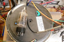
When the idea for what I now call UNSET was starting to gel inside my ADHD powered brain, I simply put a source and sink mosfet pair on G1 and G2 and a p-fet follower on the cathode of a typical TV sweep tube. I then tried every possible combination of drive polarity over a range of voltages and currents to stumble upon some ideas that could work. Each circuit combination that showed signs of usability was explored in detail. The original thought was to find a way of running TV sweep (line output) tubes in triode mode despite their low screen grid voltage rating. This test board can be seen in post #8 of this thread. It was fetched from my junk drawer for that picture so it's missing some of the parts used in the original experiments.
https://www.diyaudio.com/community/threads/desoldering-compactron-sockets.402388/
The combination of cathode drive, "Schade" feedback directly from plate to G1, and a fixed ground referenced DC voltage on G2 turned out to be the best configuration tested. I named it UNSET since it provided Single Ended Triode like curves from a pentode tube with pentode like power output and eliminated the need for negative bias voltage.
It may not be obvious but in this case both G1 and G2 see drive signal voltage with respect to the cathode while plate to grid negative feedback is also independently applied to G1 without any capacitors in the path to cause phase shifts at the frequency extremes. Hand traced curves on a sweep tube do look just like a triode. The spacing errors are due to inaccurate voltage settings on a cheap power supply while rushing the test to avoid melting a tube being tested far beyond its ratings. The "Mu" can be adjusted with the feedback resistor ratio.
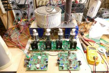
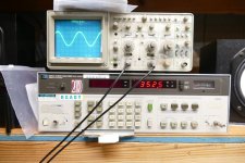
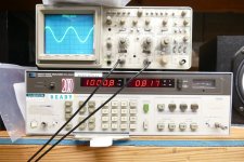
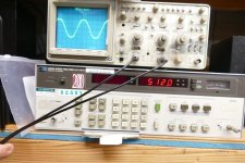
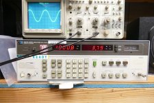
These pictures show 512 watts of audio power flowing from 4 X 26HU5 TV sweep tubes at under 4% THD, and 0.82% THD at 350 watts. That's about equal to or better in terms of THD than what I can squeeze out of them in pure pentode with conventional G1 drive. Clipping becomes evident at 525 watts. Note that it is still rounded off due to the direct feedback path.
Attachments

Thanks for a very detailed answer!
"It may not be obvious but in this case both G1 and G2 see drive signal voltage with respect to the cathode"
Yeah, that makes sense. I confused things with the UL-action one gets from using CFB and a G2 voltage that is fixed WRT ground, but here the phase relationships must be inverted due to the cathode grid?
- Home
- Amplifiers
- Tubes / Valves
- 6GB5 and Variants as Screen Driven Amps