If the heaters are in series then they only need 1.8 amps of current. I'm beginning to wonder if you are experienced enough to be playing with 1000 volts... 😱I beg your pardon. I am a neophyte.
I beg your pardon. I am a neophyte.
 a neophyte and 1kv do not go together well, for your own safety i urge you to desist and do something else....
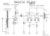
I've had problems with damper diode filaments wired in series in the past. I recommend two in parallel on separate windings; one filament transformer for each channel. You might have a look at the Russian 6S22 rectifier diode if you can find them.
At these voltages (around 1kV) I like to place the chokes in the negative rail to reduce voltage stress on the choke insulation.
I use CLCLC in my GM70 power amplifier supplies, rectification is by solid state bridge from an untapped winding to improve transformer reliability and keep size/cost reasonable. The hybrid bridge you are using is a good idea for the same reasons.
I was relieved to hear that you are having someone experienced build the amplifiers for you. You really ought to learn to solder; just not on this project. 😀
Thank you all for the advice. I need to retrieve a safe design of my amp Single Ended Parallel GM70.
Then I will build everything by paying an expert (I do not know a weld). I'm just here to learn. 🙂
All wiring related to the HV circuit must have at least twice that level of voltage rating, including the heater circuit.
Observe appropriate clearance and creepage in HV circuits. Use discharge resistors on power supply capacitors.
Input grid should have a resistor to ground to ensure voltage at grid is defined independent of switch.
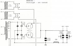
The ground goes after the last choke in the filter string whether CLC or CLCLC! (only) 😀
Also only a single pair of silicon diodes are required if you do not have a separate secondary for each channel.
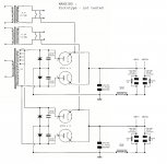
Consider building monoblocks due to weight of all that iron; I've carried it one step further and built on 4 chassis per stereo pair.
Also only a single pair of silicon diodes are required if you do not have a separate secondary for each channel.
Consider building monoblocks due to weight of all that iron; I've carried it one step further and built on 4 chassis per stereo pair.
kevinkr: for the ground connection I think I understood (see drawing right)
Rayma: I did not understand much of what you said. I do not know the English language and are forced to udare automatic translator Google (with all the distortions of language imaginable). It would be pleasing to publish a drawing to make full understanding. Thanks
Rayma: I did not understand much of what you said. I do not know the English language and are forced to udare automatic translator Google (with all the distortions of language imaginable). It would be pleasing to publish a drawing to make full understanding. Thanks
Attachments

Yes, that is what I meant.
I also recommend two high separate voltage secondaries, one for each channel, and CLCLC filtering to minimize noise.
Your driver stage should probably have a separate (lower voltage?) supply.
I am not sure about your choice of 6HV5A as the driver tube. Your usage is far outside of what is typical usage for this type and I have no clue as to whether it is sufficiently linear for this use or not.
I have been running a pair of KT120 PPP differential mono-blocks for several years with a hybrid bridge like you propose to use. I'm using DSE160-12A hexfreds for the SS half. After a failure short I had to replace the single rectifiers with two connected in series with 1M voltage equalizing resistors. So your choice of a beefier rectifier is warranted. I would suggest you consider using a choke with a double coil like the Lundahl LL1638 http://www.lundahl.se/pdfs/datash/1638.pdf. These chokes can be wired with one coil in series with the positive half of the bridge and one in series with the negative half for better common mode rejection (see bottom of data sheet). I have found that this arrangement gives quieter backgrounds and better depth to the sound stage.
I wouldn't particularly at the voltages involved due to insulation stress and if wired for common mode rejection the chokes will have no differential mode rejection (ripple is differential mode) and if wired for diff mode no common mode rejection.
I place them in series on the negative side of the rail in a CLCLC configuration (you would use two separate chokes) for ripple suppression. SE amplifier circuits have very poor power supply noise rejection and need very clean DC.
A small differential choke may be a good idea, I have not tried it so I do not know for sure. I would separate the functions of line filtering from ripple reduction.
revival56 - Yes you have it right.
"I wouldn't particularly at the voltages involved due to insulation stress and if wired for common mode rejection the chokes will have no differential mode rejection (ripple is differential mode) and if wired for diff mode no common mode rejection."
If you read the data sheet the Lundahl choke is rated for 2kV. They can handle the voltage stress. As to ripple reduction you are confusing energy storage with cancellation. When the chokes are used in the common mode connection their energy storage capabilities are not diminished at all. However, you are correct when you write that used in the “normal” mode there is no common mode rejection to speak of.
Last edited:
.
I place them in series on the negative side of the rail in a CLCLC configuration (you would use two separate chokes) for ripple suppression. SE amplifier circuits have very poor power supply noise rejection and need very clean DC.
.
Is there an advantage in placing the chokes on the -ve rail? I've seen this done occasionally but never understood why.
It reduces the voltage stress between the coil and the frame (which is bolted to chassis, i.e. ground), and helps to keeps ripple current out of the audio ground. Also, if you put a choke or resistor in both the ground and high-voltage paths, then you create an excellent barrier against common-mode leakage currents coming from the mains supply.Is there an advantage in placing the chokes on the -ve rail? I've seen this done occasionally but never understood why.
Last edited:
It reduces the voltage stress between the coil and the frame (which is bolted to chassis, i.e. ground), and helps to keeps ripple current out of the audio ground. Also, if you put a choke or resistor in both the ground and high-voltage paths, then you create an excellent barrier against common-mode leakage currents coming from the mains supply.
Thanks, Merlinb.
So is there any reason NOT to do it? I assume the ripple reduction in the B+ is the same either way?
Nothing that springs to mind. Sometimes the amp runs directly off the reservoir cap in which case you obvously can't do it, and sometimes you have a bias supply derived from the same transformer winding, which confuses matters if you have something in the ground side of things. But if you can do it, I think it is usually worth it.So is there any reason NOT to do it?
- Status
- Not open for further replies.
- Home
- Amplifiers
- Tubes / Valves
- 6CJ3's in full wave rectifier