
Yes that looks OK, I would recommend stacking 3 or 4 resistors in series on each cap for bleeders as most individual resistors do not have sufficiently high voltage rating. (I use three 450V rated 2W resistors in series for each cap.) You can make this a note (nota bene nb) in your schematic.
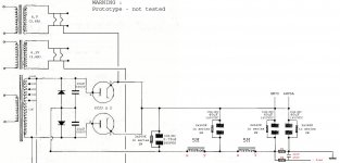
No way!! 470R resistors, are you mad?! Here:I modified stealing from a similar scheme that is statp published in a magazine of sound construction. Look a little if that further resistance from 20K-5W I designed the first capacitor filter is good for something.
Or if it's better without.
Attachments
OK! true! Last night I collapsed from sleep and in redesigning the scheme I did a bit of confusion ... 
merlinb : "Nothing that springs to mind. Sometimes the amp runs directly off the reservoir cap in which case you obvously can't do it, and sometimes you have a bias supply derived from the same transformer winding, which confuses matters if you have something in the ground side of things. But if you can do it, I think it is usually worth it."
Through automatic translator can not understand completely the messages, difficult to translate to the technical content. In the cited text talking about bias.
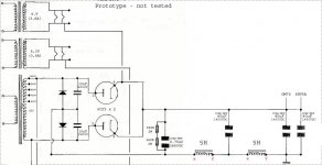
You can obtain it in this way (with the inductors on the negative side)?
Or in this way is to avoid?
Through automatic translator can not understand completely the messages, difficult to translate to the technical content. In the cited text talking about bias.
You can obtain it in this way (with the inductors on the negative side)?
Or in this way is to avoid?
Attachments
I've been looking at the 6CM3 as well, and it's counterpart the 6DN3 both have similar ratings, 5500 peak inverse plate voltage, 400mA average plate current, and the same heater-cathode ratings as the 6CJ3. Both the 6CM3 and 6DN3 datasheets show a Peak plate current rating of 1700mA.
These don't seem to be as common, but I can see that there is some cheap availability. It's got a higher heater requirement of 2.4A, but that's not a big deal.
Then I think I'll be able to go with a 1420VAC HT winding and a 15uF first capacitor.
Thanks for the help everyone.
So.. Jumping back to the start of the thread.. I got some 6CM3's, and they don't look like I had expected.. It seems like there are 2 big plates in them.. Is this normal? I had expected to only see one.
It's hard to see the label in the pictures, but it definitely says 6CM3.
http://i.imgur.com/PrRjvv4.jpg
http://i.imgur.com/rOftOqs.jpg
http://i.imgur.com/vxTLN5s.jpg
The 6CM3 I have has 2 plates, pin2 goes to one plate and pin7 goes to the other, with the plates tied on the copper in your first picture. The cathodes are also tied and the filaments are tied. It's so close to being a FW rectifier.
The 6CM3 I have has 2 plates, pin2 goes to one plate and pin7 goes to the other, with the plates tied on the copper in your first picture. The cathodes are also tied and the filaments are tied. It's so close to being a FW rectifier.
Alright, thanks for the info. That makes sense.
I'm using 6CM3s in my amps (switched from 6550s to KT120s and upped the bias). I have tubes with the 2 plates as you describe and some with a single plate. The Hitachi tubes have the double construction, The GE and Sylvania the single plate. BTW, the Syl. tubes have the nipple on top, the GE and Hitachi on the bottom.
Just thought I'd post a follow up on this. I just prototyped my power supply over a 5K ohm 225W dummy load, I wired up the 6CM3's with cathode tied to heater and no CT connection as suggested and it worked great!
Only thing that kind of shocked me is how high my voltage is! I'm using a Hammond 724 (750 - 0 - 750V secondary) I modelled my power supply in PSUD2 taking into account the fact that the Hammond 724 is set up for 115V on the primary winding, and I have 120V in the house. So I had estimated and modelled my power supply around a secondary voltage of 782 - 0 - 782...
This was still way off.. I'm not sure why the Hammond 724 would be so far off, but I'm measuring 835 - 0 - 835V on the secondary..
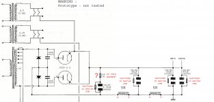
So as it stands I'm measuring 1024VDC over a 5K ohm dummy load.. with this power supply:

Is it normal that this power transformer would be so far from spec?
Only thing that kind of shocked me is how high my voltage is! I'm using a Hammond 724 (750 - 0 - 750V secondary) I modelled my power supply in PSUD2 taking into account the fact that the Hammond 724 is set up for 115V on the primary winding, and I have 120V in the house. So I had estimated and modelled my power supply around a secondary voltage of 782 - 0 - 782...
This was still way off.. I'm not sure why the Hammond 724 would be so far off, but I'm measuring 835 - 0 - 835V on the secondary..
So as it stands I'm measuring 1024VDC over a 5K ohm dummy load.. with this power supply:
Is it normal that this power transformer would be so far from spec?
I did some back of the envelope calcs, and my figures agree with your results. As for what's going on here, Hammond has had some QC issues lately. If this is an older model, it's highly likely it was designed with a mains voltage of 110Vrms in mind. I got some overvoltage out of a vintage Stancor PTX intended for 117V operation, but it wasn't enough to bother with. Restorations of really old radios sometimes calls for the inclusion of a voltage bucker in the primary to get the rail back to design nominal. In this case, a stock 12.6V PTX would do the trick here.
Back in "the day", there wasn't much standardization for mains voltage, especially for residential feeds. You'll see figures like: 110V, 117V (there's even a family of VTs designed for 117V heaters) and 120V. It's also possible that this PTX was designed for 108V operation, as that's one of the voltages you see a lot in three phase systems.
It's also possible that your mains voltage is higher than it should be. Once, I did a repair job on an electrically heated dryer, and the client was complaining about how so many heating elements were poofing. His mains voltage measured at 180Vrms. I told him to contact his provider to complain about this before even more stuff got ruined.
Thanks for the info. I've measured my wall AC and it's right on the nose 120VAC, I'm not measuring with a true rms meter or anything, but it does seem to usually be quite accurate with expected to actual meter readings.
I had heard of Hammond quite often having the primary wound for 115V mains, but not 110 or 108. I'm not concerned about the higher voltage as I can work with it, my only concern is if it was indicative of some sort of actual issue with the transformer.
- Status
- Not open for further replies.
- Home
- Amplifiers
- Tubes / Valves
- 6CJ3's in full wave rectifier