Here is the schematic I have so far. The pot will be used to adjust the 6CD6GA screen to about 10V to get the desired idle current. The cathode follower current source loading allows me to adjust the grid voltage on the follower for proper 6CD6 screen voltage without the cathode follower bias current varying all over the place. Power supply schematic will follow.
Attachments
This effort is not dead, just slow... I've simplified the schematic on both the amplifier and the power supply for my first effort. I'll post schematics and pics when the thing is up and running. It looks pretty utilitarian (gentle euphemism for butt-ugly), as I'm using a recycled chassis.
To stir the pot a bit, go to http://homepages.ihug.co.nz/~rwillis/alex/6cd6_loften_white.html and you'll find a simple schematic for an SE amp using a 6CD6 in ultralinear mode (perfect for one of the Edcor transformers with a tapped primary). The author claims about 10W RMS capability, but I don't know whether the amp in question was actually built. It certainly looks simple enough to try.
To stir the pot a bit, go to http://homepages.ihug.co.nz/~rwillis/alex/6cd6_loften_white.html and you'll find a simple schematic for an SE amp using a 6CD6 in ultralinear mode (perfect for one of the Edcor transformers with a tapped primary). The author claims about 10W RMS capability, but I don't know whether the amp in question was actually built. It certainly looks simple enough to try.
I see the schematic, and I see the claim of 10 watts RMS, but I don't see where they come from.
Lets say that the 6CD6 posses this magical abillity to fully conduct (saturation voltage of zero). This means that when the grid is driven positive, the plate voltage equals the cathode voltage ( this is really impossible). This puts the plate voltage at 80 volts. Now as the grid is driven to cutoff the inductance in the primary will take the plate voltage an equal amount above the supply voltage (assuming no distortion) This puts the plate voltage at 420 volts. The peak to peak plate voltage swing is 340 volts. The RMS plate voltage swing is 120.6 volts. The given primary impedance is 8K ohms for an impedance ratio of 1000:1 with an 8 ohm load. This gives a turns ratio of 31.6. Dividing the RMS plate voltage by the turns ratio gives 3.81 volts RMS delivered to the load. This works out to 1.8 watts, not quite 10. Remember this was with a "perfect" tube and transformer.
Now I don't mean to bash this design. In fact I might even build one, just because it is so simple. I just know from my brief torture testing that I had to operate the poor tube well into the red glow region to get anywhere near 10 watts. I think that the load impedance needs to be far lower to get more power.
It may be closer to realization with 400-500V B+ and a 5k transformer. I personally would not like to push the plate voltage down past ~100V on the low side. Still, a simple design, and those Edcor transformers are cheap enough to make the experiment relatively painless. I'd probably use something other than the 6K5 for the front end, as I don't happen to have any on hand. A triode-strapped 6AH6 or 6AU6 comes to mind....
I've been looking at that simple ultralinear design some more and I better understand tubelab's reservations about it. .
Unless you get your hands on a better 6CD6 than the one tubelab played with, the screen grid might just become a second filament at 275V. Also, the direct coupling between stages forces one to have an huge amount of bias at the cathode, eating up voltage margin you didn't have anyway. This design would be more appropriate for something like an 807 or 1625, both of which have 300V rated screens. I would also hang a cap between stages and use fixed bias only or fixed bias along with a more modest amount of bypassed cathode bias, with a larger bypass cap to boot.
As tubelab pointed out, a lower transformer impedance is necessary in order to better use the limited amount of voltage swing available from the relatively low B+ value. 2.5k or 5k primary impedance is better suited with this design. 5k looks like it will get you 5-6W with about 300V B+. I have some 807s and 1625s (same thing, really) sitting around looking for something to do. If I can find an appropriate piece of power iron in my junk pile, I'll buy a couple of the cheaper Edcor transformers and try to get this to work after the 6CD6 design. Of course, tubelab will probably beat me to it....
Unless you get your hands on a better 6CD6 than the one tubelab played with
I tried about 5 different kinds, with similar results. I have about 25 NOS Dumont (Sylvania) 6CD6GA's and about 50 25CD6's so I will eventually build something with them. I have been experimenting off and on with a screen driven P-P amp that currently runs 6AV5's. It runs on the edge of class B, so plate and screen dissipation is not an issue. I think the tubes with the hypersensitive screens will work good here, so I may try the 6CD6's in this design. Even with the 6AV5's I can get 80 watts, so I need to find a bigger OPT.
Of course, tubelab will probably beat me to it....
I have lots of 807's and an even bigger pile of 1625's, and I just built this SE UL amplifier that uses 6L6's and Edcor transformers. If you really want me to I could wire in one of those tubes, but I am itching to try a 6LW6. They are the king of sweep tubes.
Actually I have already tried 6L6GB tubes. It has been argued back and forth that they are (or are not) the same as an 807. It is my belief that they are the same (based on dissecting some broken ones). My operating point is a little to hot for these tubes, so I didn't play them long, but they do sound great. With 410 volts across the tube, 60 mA current, and a 5K load, I get about 10 watts in UL and 5 in triode, at 5% dist. That is a little too much power dissipation for an 807, so you would need a little less voltage or a bigger cathode resistor (currently 560 ohms).
The schematic for the PC board (transformer and switch connections are not shown) can be seen here:
http://www.tubelab.com/SimpleSE_schematic.htm
Tubelab,
The simple amp at your web site looks pretty much as I envisioned it would be, except for the current source loading on the input stage. I might try this on my version using a LV JFET current source cascoded with a PNP bipolar.
I looked up the specs on the 5842, and it is an interesting little beast indeed. It has a nice combination of low Rp, high gm, and reasonable gain. What I'll probably end up using in my setup is a triode strapped 6AH6. The mu is around 40, the plate resistance is not too bad (~3k), and the gm is respectable. I also have a bunch, which is more than I can say for either the 5842 or 12AT7. I'm also interested in the possiblility of triode strapping a 6AK5 (I have a bunch of these too, and they're cute little devils), but I don't think the specs will be as good as the 6AH6.
A local surplus outlet has some small cheap 115/230V stepdown transformers. If these have isolated windings, I'll press one into service for my plate supply. With a full wave bridge output, one of these would give me about 330V B+, which is just what the doctor ordered for both input and output tubes. If I put the 6AH6 filaments in series, I could run them and a pair of 1625s off a separate 12V transformer.
I just finished doing some curve plotting for the ultralinear amp mentioned above, using the 807 curves for G2 = 300V. I used 330V B+, 60mA bias current, which is right at the tube dissipation limit. With a 5000 ohm primary impedance, it looks like one could eke out about 5-6W RMS, assuming there isn't a lot of loss in the transformer primary. The amp would really like more B+ (say 400V), but this exceeds both the screen and dissipation limits. I don't know how that Kiwi designer ever thought he could get 10W at a much lower B+. Right now I'm thinking of using a Magnetek isolated 115/230V transformer that I picked up for 8 dollars. In step-up mode, rectified and, filtered, this gives me 320-340V, depending on my line voltage. It has way more VA capacity than I need (175 VA), but the price was right....
6CD6GA
Hi,
I am using these nice valves as substitute of EL34 on a PP-UL amplifier. B+ is 410 Volts and current 40mA, they are glowing blue (mine are 4 Philips) but sound much better than EL34. Pout i think is 45 W pch.
Ciao
Alberto
Hi,
I am using these nice valves as substitute of EL34 on a PP-UL amplifier. B+ is 410 Volts and current 40mA, they are glowing blue (mine are 4 Philips) but sound much better than EL34. Pout i think is 45 W pch.
Ciao
Alberto
Boy oh boy, this amp has certainly been through a lot of changes since I started it (quite a while back). The current design (4th iteration or so) uses a 6JC6A frame-grid pentode to directly drive the screen of the 6CD6GA (the 6JC6A is another one of those "little pentodes that could", just like the 12HG7) . The design was inspired by Peter Millett's SE triode-connected 813 amp using a 12HG7 as input/driver stage. The screen grid bias resistor on the 6CD6 is only 33k, connected to a pot from a +36V regulated supply, (bypassed by a big cap) for bias current adjust. Screen current draw appears negligible at ~ 20V screen bias. I'm shooting for ~60 mA quiescent current in the output stage, which should net me about 8-9W/channel. I'll post a schematic when I'm more sure about resistor values. I'm using a mixture of fixed bias and cathode bias in the output stage, and will probably cut the cathode resistor down to 100 ohms from 120, so I have more freedom for bias adjustment.
One thing I've found is that the GE 6CD6s I have on hand require substantially less positive bias for the same plate current than the RCAs. I originally plotted screen-driven curves for the 6CD6GA using a GE sample, and used these curves to plan for the screen bias. No biggie, since I wanted to use the GEs anyway, and only had the RCAs in place as sacrificial goats while I was tuning in the circuit. Anyway, the GE tubes are in place and the output stage bias is where I want it. Next is to apply a signal with a resistive load and look at open loop gain, also sniffing around for antisocial behavior such as oscillation in the input tube. If all looks well, I'll close the loop, dress the wires, and try to drive some speakers. Finally! This was supposed to be my first quickie tube amp - instead, it's a rather distant second. The "Shrine" was my first, and is still doing duty in my living room.
One thing I've found is that the GE 6CD6s I have on hand require substantially less positive bias for the same plate current than the RCAs. I originally plotted screen-driven curves for the 6CD6GA using a GE sample, and used these curves to plan for the screen bias. No biggie, since I wanted to use the GEs anyway, and only had the RCAs in place as sacrificial goats while I was tuning in the circuit. Anyway, the GE tubes are in place and the output stage bias is where I want it. Next is to apply a signal with a resistive load and look at open loop gain, also sniffing around for antisocial behavior such as oscillation in the input tube. If all looks well, I'll close the loop, dress the wires, and try to drive some speakers. Finally! This was supposed to be my first quickie tube amp - instead, it's a rather distant second. The "Shrine" was my first, and is still doing duty in my living room.
Measurements tonight indicate an open loop gain of 15X, which doesn't give me a whole lot of room for negative feedback to tighten up the bass response and lower the output impedance. I could shift a couple of wires in the filament supply and drop in a pair of 12HG7s in place of the 6JC6 input tubes, which would almost double the open loop gain. I may try just that to see how much juice I can squeeze out of a simple circuit before resorting to more desperate expedients like dropping a follower stage between the input and the 6CD6 output.
On a brighter note, the waveforms I've measured look reasonably clean, with no tendancy to run away and tweet RF-wise.
On a brighter note, the waveforms I've measured look reasonably clean, with no tendancy to run away and tweet RF-wise.
Well, last night I tried a 12HG7 in place of the 6JC6A, without a substantial gain increase, probably because the tube is running only at 9-10 mA plate current. There is also clipping at the positive peak of the output waveform due to the screen current draw.
Peter Millett got around this in his 813 design by using the 12HG7 with high plate current and smaller plate resistor. I don't feel like blowing all that power in a plate load resistor, so I'll opt for the chicken-livered approach of inserting a source folower between input tube and output.
I'll switch back to the 6JC6A input tubes and save the 12HG7s for a situation where I need a bigger gun. The follower will need a different supply with some negative bias, but I think I have just the little transformer for the job - I'll know tomorrow. I'm eager to finish this amp, so I can get it off the bench and move on to some of the other projects I have lined up for completion.
Screen Driven 6CD6 (Introducing Miz Piggie)
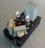
Attached is a picture of my screen driven 6CD6GA SE amp, "Miz Piggie". She is in debug stage - one side biases up ok, the other has a problem with the source follower driving the screen. As soon as I fix this and check for hmmmm, I'll post the schematic. Front end uses a 6JC6 video driver pentode, follower by a source folower directly coupled to the screen of the 6CD6. I call her Miz Piggie 'cause she weighs a ton with that big, grey power transformer on top. The output transformers are no slouches, either.
Attached is a picture of my screen driven 6CD6GA SE amp, "Miz Piggie". She is in debug stage - one side biases up ok, the other has a problem with the source follower driving the screen. As soon as I fix this and check for hmmmm, I'll post the schematic. Front end uses a 6JC6 video driver pentode, follower by a source folower directly coupled to the screen of the 6CD6. I call her Miz Piggie 'cause she weighs a ton with that big, grey power transformer on top. The output transformers are no slouches, either.
Attachments
If you are short on gain, you could try the scaled g2/g1 drive scheme floating around lately. Since you have the source followers already, just use a resistive divider from that (g2) down to some bias voltage to derive the signal for the g1. This would be scaled approx. as the Mu between g2/g1 so that each grid would be having the same effect. That way only half as much original drive swing is required on the g2's. George was going to try Mosfet followers for the g1s too, but probably not necessary for a dedicated design.
Don
Don
With the pentode input stage, and the source follower to lightly load it, I'm not likely going to be short on gain. The 6JC6 has a lot of transconductance - that's why I'm using it. This design is single ended, after all, so a whole lot of positive drive will be wasted. I only need about 20-30V or so P-P to run the tube from maximum current to cutoff. I really want the extra gain around to have some to feed back, as the screen driven 6CD6 has a pretty high plate resistance, and I don't want to go to all this trouble just to end up with flabby bass. Screen bias is 10-12V on the side that's working correctly, for a bias current of 60mA. Since the B+ is around 400V, this is technically over the 20W plate dissipation rating for the 6CD6GA, but I'm using GE tubes with big plates, and they show no signs of distress. The screens are just fine, of course.
When I was messing around without a follower, the positive excursion was being rounded off via the loading imposed by the 6CD6 screen current draw. I was also using a relatively small value screen resistor , so this was limiting gain as well. The source follower fixes all this. I just need to get both sides working right so I can start hammering on the thing and get some real data. It looks preliminarily like the follower MOSFET is shot on one side for some reason. Since the followers are each on its own "stewie" board, I can take the offender back out and bias it up on the bench.
When I was messing around without a follower, the positive excursion was being rounded off via the loading imposed by the 6CD6 screen current draw. I was also using a relatively small value screen resistor , so this was limiting gain as well. The source follower fixes all this. I just need to get both sides working right so I can start hammering on the thing and get some real data. It looks preliminarily like the follower MOSFET is shot on one side for some reason. Since the followers are each on its own "stewie" board, I can take the offender back out and bias it up on the bench.
Here's the schematic for the Missus in my own scrawly hand - nothing really remarkable going on here. This or something very close to it may become my basic schematic for dealing with SE screen driven sweep tubes if it sounds ok. I'll know that by the end of the week. The high gm video pentode tubes are very plentiful and very cheap - I may use one as a front end for a future 6HV5A SE amp, as the pulse mode beam triodes have some similarites to screen driven sweep tubes (though much higher gain and gm).
Attachments
After fixing some silly-a** mistakes, the missus is up and running. There'some hmm, but also some nice, crisp sound. Square wave response is exceptional, even with the so-so Hammonds 125 series output transformers. I'm bringing it to work tomorrow, both to audition it on some speakers there and to try running the filaments with DC in an attempt to do a little hum isolation. Both channels hum about equally with no input. I'm hoping it's not the HV smoothing.
I have two 6V windings on the monster power transformer poking out the top of this thing- it would be a good experiment to run the filaments in series, especially as the 6CD6s suck up 2.5A apiece - definitely one of the drawbacks of messing with sweep tubes.
I have two 6V windings on the monster power transformer poking out the top of this thing- it would be a good experiment to run the filaments in series, especially as the 6CD6s suck up 2.5A apiece - definitely one of the drawbacks of messing with sweep tubes.
Miz Piggie was greatly appreciated at work today, and may have won some converts over to he tube side of the force. I drove a pair of so-so Infinity speakers using a portable CD player loaded with some jazz bombshells from Kahil El-Zabar (the Delmark label rules - check it out). The hmm is not so bad (though I may be able to better things by re-routing some wires), and imaging and placement of instruments is excellent. Not bad for ultra-cheap TV tubes in A2 mode, with a pentode front end. I'll be bringing the missus to Burning Amp, along with a couple of less massy brothers and sisters. Look for me there...
I looked at the output hmmm oin a scope, and it looks to be a faithfiul replica of the ripple on the HV supply (a sawtooth with softened edges), and about 50-100mV p-p. It looks like some extra filtering is in order on the 400V supply. I have the bias set now near 70mA per tube, so the inductance needed for a CLC filter is likely to be fairly modest. I have a PFC inductor from a PC power supply sitting on my bench that might be worth a try.
- Status
- Not open for further replies.
- Home
- Amplifiers
- Tubes / Valves
- 6CD6GA in Enhanced Triode Mode for SE Amp