sser2,
That method of finding the choke parameters works.
One thing that does change, is the inductance varies with DC current applied.
I used to find that most output transformers I tested had self resonance frequencies of from 500Hz to 3kHz, most often from 1kHz to 2kHz.
For those who are worried, when the transformer is driven from the proper impedance, and loaded with the proper impedance, that resonance is swamped out (not a significant factor).
Last edited:
Many thanks. Do you think a good, conventional output transformer would have better data compared with a good anode choke when it comes to bandwith and resonance peaking?
Hands down. A choke has to deal with DC, whereas differential transformer doesn't, in a big picture of things. Theoretically, you can make a better choke by using a very highly sectioned winding and avoiding turn-to-turn arrangement, but you will have to wind it yourself.
Another problem of a choke wound on a conventional core is magnetic permeability collapse at higher frequencies due to thick laminations. In a transformer, it doesn't matter.
Schmitz77,
Your schematic in Post # 19 there no signal being applied to the dual triode's 2 grids . . .
Incomplete schematic.
If you apply out of phase signals to that dual triode stage . . .
Then that circuit is a "Balanced Amplifier".
Since the cathodes returned directly to ground (in this case both DC and AC ground), and there was no constant current source from the 2 cathodes to ground, that stage is Not a "Differential Amplifier".
Schmitz77,
The 2 triode amp in your post # 19 is Not a Differential Amplifier.
If you drive the two grids with equal amplitude signal of opposite phase, it is a
Balanced Amplifier (if all the other circuit parameters are equal, such as plate loads).
*** A common mode signal to both grids has output signals at both plates.
A Differential Amplifier has to have a single Constant Current Source from the parallel connection of the 2 cathodes, with the other end of the CCS connected to ground.
+++ A common mode signal at both grids, does not have any output signals at both plates.
Compare *** to +++.
I recommend you go to your library and see if they have one of the yearly editions of the ARRL Radio Amateurs Handbook from the 1950s to the early to mid 1960s.
If they do not have one, then go online and purchase one there.
It has electronic theory, resistance, capacitance, inductance, DC, AC, reactance, resonance, Tubes, Tubes, power supply design, audio tube and RF tube design, and other practical information.
I got started in electronics with a 1956 copy, and then was given a 1959 copy.
If you can not get one of those old copies, at least purchase a new copy. Much less Tube information, but lots of theory and practical circuits.
Last edited:
sser2,
Thick Laminations work pretty good for 60Hz power transformers, and for 120Hz chokes.
Thick Laminations do not work well for 20Hz to 20kHz output transformers.
Too much insertion loss caused by the laminations.
Thick Laminations work pretty good for 60Hz power transformers, and for 120Hz chokes.
Thick Laminations do not work well for 20Hz to 20kHz output transformers.
Too much insertion loss caused by the laminations.
sser2,
OK, Now we have a number, not a relative but unmeasured value.
What I always did before I used a choke as a constant current source, is measure the impedance from 20Hz to 20kHz.
That told me if there were loss issues, and if there were distributed capacitance issues that would prevent the choke from being a good fit for the application I used it for.
Of course, the DC current and low frequency was a separate issue. Inductance at 120Hz and a DC current level, is far different for the same current level at 20Hz. Very conservative current levels applied, versus the rated current level, makes for good low frequency performance with DC current applied.
Last edited:
My Lundahl chokes are build the same way as their output transformers are mostly build. For some types they use kraft paper between winding rows, but for others they have some sort of foils between the layers, so I don't think that their chokes have narrower bandwith compared to their signal transformers.
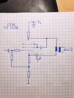
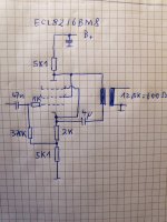
Anyway, I've spotted cheaper chokes in gear, in this case it would be an anode choke for an ECL82 and it looks much cheaper compared to the Lundahl ones. And still its working sufficiently.
Anyway, I've spotted cheaper chokes in gear, in this case it would be an anode choke for an ECL82 and it looks much cheaper compared to the Lundahl ones. And still its working sufficiently.
One solution for HF problems of a plate choke is adding a second series choke of lesser inductance, but designed specifically for high frequency. An example could be a choke with sectioned winding, wound on gapped ferrite or amorphous core with silk-clad wire.
Last edited:
sser2,
Decades and Decades old, before many were born . . .
Take a look at the 2MHz to 30 MHz "Christmas Tree" RF chokes for the idea.
Those many many separate groups of windings worked very well, there was plenty of choke groups that did not all self resonate at any chosen frequency, 2-30MHz.
For so many choke applications, even a good power supply choke works very well.
I have proved that a number of times.
Be careful:
All power supply chokes are equal, but some power supply chokes are more equal than others. George Orwell, "Animal Farm" and modified by me.
Lundahl uses turn-to-turn winding layers. Turn-to-turn capacitance is major contributor to overall parasitic capacitance; layer to layer only minor.
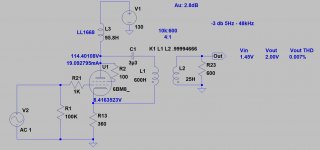
I have LL1668 choke (100H), measured it with DER EE DE-5000 LCR meter:
95.8H; DCR:668; RP: 576k; Cp: 42.6pF
It's enough good for anode choke.
How did you measure winding capacitance?
sser2,
Decades and Decades old, before many were born . . .
Take a look at the 2MHz to 30 MHz "Christmas Tree" RF chokes for the idea.
Those many many separate groups of windings worked very well, there was plenty of choke groups that did not all self resonate at any chosen frequency, 2-30MHz.
For so many choke applications, even a good power supply choke works very well.
I have proved that a number of times.
Be careful:
All power supply chokes are equal, but some power supply chokes are more equal than others. George Orwell, "Animal Farm" and modified by me.
Those RF choke's had much fewer turns than audio chokes, hence lower capacitance.
In addition to sectioning, they were wound with silk-clad wire using "universal" technique to reduce capacitance. The sections were of progressively decreasing size, so that larger ones take care of lower frequencies, and the smaller ones of the higher, same principle as audio choke's in series.
LCR meter at 100kHz.How did you measure winding capacitance?
It's enough good, I checked it years ago with resonance measurings.
That means they have something in their sleeve re. winding sectioning. 50H audio choke from the UTC catalog has about 1000 pF, from their Q plot.
Lundahl isn't using bobbins and he has developed machines for automatic winding, layer by layer. Each layer is isolated with a plastic foil or kraft paper, like it was done in old times. Its not random winding like in cheap PSU choke coils using bobbins.Lundahl uses turn-to-turn winding layers. Turn-to-turn capacitance is major contributor to overall parasitic capacitance; layer to layer only minor.
P. S. Still don't have a clue why someone mix a cathode follower with an anode load resistor. Its no phase splitter, nor makes use of the cathode followers low impedance output. But it must be something very special, the amps were talking about cost a fortune.
Someone got an idea? Whats the big advantage here?
Attachments
Last edited:
LL1667 and 1668 has two coils.
Connected its serial (270H and 100H), each winding capacitance also will be serial, so the result enough low.
Connected its serial (270H and 100H), each winding capacitance also will be serial, so the result enough low.
- Home
- Amplifiers
- Tubes / Valves
- 6BM8/ECL82 parafeed line output