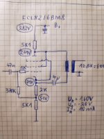
OK, my fault. Too low anode voltage.
New operating point for the tube should be 160V/10mA/-20V, so that should work better and are the values, that are being used by famous ampmaker.
Maybe we'll get something usable here instead of an attenuator?
Many thanks for your help!
New operating point for the tube should be 160V/10mA/-20V, so that should work better and are the values, that are being used by famous ampmaker.
Maybe we'll get something usable here instead of an attenuator?
Many thanks for your help!
Attachments
Last edited:
OK, many thanks Euro 21!
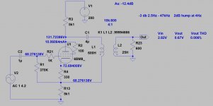
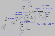
What we've got here (without C3!) is a classical split load phase inverter with unbypassed cathode resistor. If it should be bypassed, then only R4 should be used, because the equal cathode and anode loads are for signal amplification positive and negative.
Gain equal to one, thats pretty normal. I think this could be usable as an output stage.
Last edited: