I just installed the FP splitter from the Acro. It was already built, I just had to install it. I use bottom mount sockets, and terminal strips with point to point wiring so I am able to remove the entire amp intact and build something else or transplant it.
I'm almost done. Just a little more wiring to do but hopefully I'll hear it tonight.
I'm almost done. Just a little more wiring to do but hopefully I'll hear it tonight.
Looking forward to seeing how it works for you.
The 6AS7 types are fun tubes for sure, hard to beat how well they work, and if you get the "G" types or Russian equivalent they are handsome too. The juice is definitely worth the squeeze.
The 6AS7 types are fun tubes for sure, hard to beat how well they work, and if you get the "G" types or Russian equivalent they are handsome too. The juice is definitely worth the squeeze.
Got it up and running. Sounds good for such a quick job. No gnfb yet. 6N13S are running 105ma with 115V across them by the looks of it. The entire app is running from SMPS, too. It's weird to lift a light tube amp 🙂 I'm using TL783 bypassed with 1000uf caps on the cathodes, and using 22R load sharing resistors on the plates in case of oscillation.
One 12V 21A SMPS powers a 500W boost converter that gives 160V, another 12V 21A SMPS powers the heaters and a boost converter that is making ~300V for the phase splitter. Not a bad amp at all so far. I haven't beat the marde out of it yet though...
One 12V 21A SMPS powers a 500W boost converter that gives 160V, another 12V 21A SMPS powers the heaters and a boost converter that is making ~300V for the phase splitter. Not a bad amp at all so far. I haven't beat the marde out of it yet though...
Last edited:
Looks good. I never used any plate stoppers, so not sure how they help in some situations. I'd be tempted to pull them out if they don't hurt being gone.
When I built a 6L6 like this using resistors instead of TL783 the tubes oscillated... In reailty the mu is so low with these you'd have to try and make it oscillate. They only drop 3V anyway though.
Well, time to put some bass heavy music through it and see how it does! These low impedance types can do some very nice bass, especially through a toroid with nice balance. The first one I built up jumped out at me immediately due to the tight, solid state type of bass response.
The bass is nice I have to admit, but I expected it to be, just not from wimpy 25VA coils... I'll upgrade them to 50VA when I can... at 200ma/side I'm at about the fully loaded primary current it would see if it was serving it's intended purpose complete with the 40c rise. I start by measuring with my ears, and then the test equipment so that'll be tomorrow for hard numbers. This is the lowest B+ voltage I've ever used but also the highest current.
Back to back 680uF caps with a 1M resistor to ground between them is what I did last time around, using savaged high voltage caps from dead/old computer PSUs. Worked very well.
I'm testing my amp now finding the high temperature... I'll run it until something fails, too lol The aluminum chassis is about 65c now...
It's sharper. Better slew rate, even in open loop. I'll snap a picture of it when I test it's max power and frequency response. Seriously though, you need to try this phase splitter, man 🙂 Of course, I'm powering it off of a boost converter. In fact, the whole amp runs from switching power. It's also the lightest tube amp I've ever seen 🙂
That feedback loop translates to 1V in for 2.8V out... My line stage is rather hot...
That feedback loop translates to 1V in for 2.8V out... My line stage is rather hot...
Last edited:
Hey Everyone,
Glad to see this thread went somewhere. The weather is getting bad so it's time for indoor activities. I'm back to my 6N13S amp. I was thinking of building as a differential amp. I have the output transformers already. They are custom Heyboer. Thirty watt, 250 ma, 3k to 8 ohm outputs. I intend to use two bottles per channel. Still intend to use TL783 as current sinks for each halve. I intend to run the tubes at 50 ma each and 250 volts B+. I know this runs against the grain but I want to see how it sounds that way.
As always I have a couple questions. I was thinking of using two 6SL7 stages for voltage amps to get the required swing. I have a box of 6SN7 and 6SL7 and tested a dozen of each. Does this tube seem like a good candidate? It has a mu of 70. Thing is I've never heard this tube so I don't know what I'm in store for.
I do have another question. My experience with solid state devices is even more limited than my tube experience. I've been told that to make TL783 work I would use the same resistor to set the current as I would if I were doing cathode bias. In this case 1500 ohms. What I am not sure of is whether with TL783 will I still drop 75 volts across the resistor? It looks as though the current path is still through the resistor so it will won't it?
The TL783 is set the same way as an LM317 for current.
Here is a calculator: LM317 Current Calculator | REUK.co.uk
According to it, and my own experience, it's ~21R, not 1500...
Regarding gain, If you don't want to use the 6F12P example above, you might use something like the first circuit in this page: Triode power amplifier.
I think the voltages will scale pretty well.
Cheers.
Last edited:
Thanks, I don't know where I was told the set resistor would be the same as cathode resistor? That makes things much easier. I've never been crazy about 12AX7. And I'd like to avoid a pentode in the circuit if I can. I'd rather do the phase splitting at the input transformer. With 6SL7 I can run a B+ around 250 which makes the power supply less complicated.
Two bottles in parallel feeding a 3K transformer shows a reflected load of 6K per triode, which may limit your power output some. I've done similar before, and it sounded good. If you have 4 ohm speakers try them on that 8 ohm secondary. I found that a 6K:8 transformer worked well with two bottles each with a 4 ohm load, at a 300 volt supply, garter biased to ~10 watts per triode. I think it needed 80~90 volts peak per grid to go to full output, and I was unable to reach this with a 6SL7 concertina, and had to run a driver stage between the two with a 6SN7 in order to get enough signal into the outputs. Power output was some ~18-19 watts if I'm not mistaken.
6SL7 may be a good choice here, but 250 volts may not be enough to get the needed swing if used in a concertina. A concertina or differential/LTP front end feeding another differential/LTP may work well, and you could use the 6SN7 for both if your source is hot enough, and overall negative feedback isn't too high. Basically a Williamson type of front end would work well, and is what I would do, with 6SL7 feeding 6SN7, and a good bit of feedback to take the edge off.
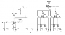
If interested, the most successful implementation I've yet to see using the 6AS7G at higher voltages is this one by Wim de Haan, attached is the schematic. His site is gone, but the wayback machine can help find it...
6AS7G based tube amplifier
Take note of the distortion measurements !
6SL7 may be a good choice here, but 250 volts may not be enough to get the needed swing if used in a concertina. A concertina or differential/LTP front end feeding another differential/LTP may work well, and you could use the 6SN7 for both if your source is hot enough, and overall negative feedback isn't too high. Basically a Williamson type of front end would work well, and is what I would do, with 6SL7 feeding 6SN7, and a good bit of feedback to take the edge off.
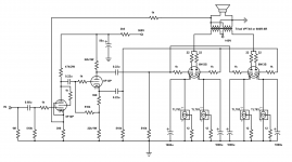
If interested, the most successful implementation I've yet to see using the 6AS7G at higher voltages is this one by Wim de Haan, attached is the schematic. His site is gone, but the wayback machine can help find it...
6AS7G based tube amplifier
Take note of the distortion measurements !
Attachments
Last edited:
- Home
- Amplifiers
- Tubes / Valves
- 6AS7GA as push pull output?