"New issue Tung Sol 6L6G" may have been the difference. Also Sweetwater sales new stuff with probably means mostly chinese tubes. I have no doubt that they're not robust enough for such circuits.
Generally speaking it's not a good idea to hear tubes without power applied unless they are specifically intended for long periods of operation under cut off condition. A good idea would be to give a lower current, moderately high (90V or so) voltage plate supply with a bias resistance or CCS to give a couple watts dissipation, or you can bake them in the oven to get the getter going.
I've found this to be unnecessary, just break them in by running them in an amplifier that runs things conservatively.
I've found this to be unnecessary, just break them in by running them in an amplifier that runs things conservatively.
I agree. My OTL's run the tubes pretty hard. Likely not the ideal conditions. I by no means recommend running them with no plate voltage for months or years. Some of the old televisions did just that. Of course you could go to the corner drugstore, test your old ones and pick up the new ones of your choice. Ahh the good old days.
The data sheet says to not apply full current until the cathodes reach operating temperature, about fifteen seconds. So hit the filament switch count ten, hit the B+.
Why would it surprise anyone that these valves would be microphonic, after all they were never intended as audio finals and would never have been optimized for silence in that application. In fact all of the design decisions that went into optimizing them for their intended purpose, series regulation, would make them susceptible to microphonics (think about that massive grid structure and huge undamped cathodes).
This is really starting to annoy me at this stage.
With all due respect, the 6AS7G was not designed for series regulation. This is a patently flase myth that simply won't die, and it is incredibly misleading to repeat it.
The 6AS7G was developed at the behest of the RCA-Victor Home Instrument division as they needed a better damper tube for their first models of postwar television sets. They specifically wanted a power triode as it gives an extra point of control over horizontal linearity.
The bean counters didn't want to use such an expensive tube (more costly than a 6L6 circa 1946-1947) and thus it was relegated to projection sets only, while small direct view sets used simple diode dampers.
The tube was then a "tube without a job". RCA tried pushing it in audio service in a pair of articles circa 1947-1948, along with regulated power supplies starting around the same time. For whatever reason the audio applications were dropped after the RC-16 (1950) tube manual, leaving only the pass element usage. And even there, the 6AS7G was soon supplanted by even higher perveance tubes.
I've built a modified version of the RCA amplifier and love it. I have yet to hear any high pitch whine, but I don't doubt that some people hear it, or think they hear it.
That's interesting! Up to now I only know from damper diodes, so I'd like to know how a triode works as a damper device in a TV flyback circuitry. Do you have any examples at hand?
Best regards!
Best regards!
KP , the Triode is capable of taking the flyback pulse (2-3 kv voltage) to a sufficient level and time that the rectifier tube in the HV supply ( 30kv ) damps the pulse.
Ok, perhaps the damper in TV's west of the Atlantic has another purpose than here.
Best regards!
Best regards!
6080 PPP Amp my Vers
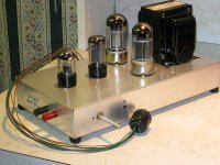
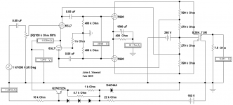
This has been on the forum a couple of times, so here it is again. I solved the drive problem with the simple fix of boot strapping, same as McIntosh & Electrovoice. So 25 Watts at clipping with 400V PS. Lots of heat from the four individual cathode resistors.🙂
The project was simply 'proof of concept'.
Attachments
Two more Bootstrapped Examples
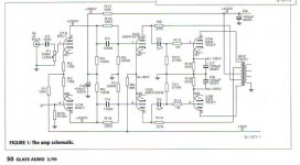
Neither of these need the UL tapped OPT I'd used in the original amp.
Using a voltage divider across the OPT primary of about 50% on each side, also calculated to give proper loading to the driver tube.
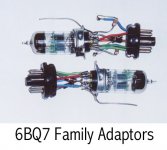
An early vers uses a pair of 6BQ7 as diff amps. This one is simulated only, I didn't do the breadboard. But I'd already made adapters to try tubes like the 6BQ7 as an alternative to the rather expensive 6SL7 & 6SN7 normally used. Tests of IMD & THD shewed the 6BQ7 to be very close in performance to what I had used on the Crowhurst Twin Coupled Amp project. In a double blind test its unlikely anyone with normal hearing would be able to hear the difference.
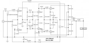
Recently I tried a bootstrapped 6SL7 driving the 5998. Worked OK, I left it at that. Depending on the supply the 5998 in PP clips at about 10 watts. The OPT was a Hammond 125E. No need for botique parts!🙂
Earlier I somehow managed to get this into another thread! How weird is that?😱
Neither of these need the UL tapped OPT I'd used in the original amp.
Using a voltage divider across the OPT primary of about 50% on each side, also calculated to give proper loading to the driver tube.
An early vers uses a pair of 6BQ7 as diff amps. This one is simulated only, I didn't do the breadboard. But I'd already made adapters to try tubes like the 6BQ7 as an alternative to the rather expensive 6SL7 & 6SN7 normally used. Tests of IMD & THD shewed the 6BQ7 to be very close in performance to what I had used on the Crowhurst Twin Coupled Amp project. In a double blind test its unlikely anyone with normal hearing would be able to hear the difference.
Recently I tried a bootstrapped 6SL7 driving the 5998. Worked OK, I left it at that. Depending on the supply the 5998 in PP clips at about 10 watts. The OPT was a Hammond 125E. No need for botique parts!🙂
Earlier I somehow managed to get this into another thread! How weird is that?😱
Attachments
I'd like to design and build by own headphone OTL tube amp - an exercise for the grey cells. I feel like I'm walking down a very worn path of 6SN7+6AS7 judging by the posts, threads and stories.
So my criteria is being able to drive 55ohm (220mW max) pair of AGK headphones - I want this due to most modern headphones (even if I replace them) are moving towards low impedence. I'm happy if there's some solid state supporting (such as CCS, recrifiers etc).
The design I'm currently exploring on LTspice is a 6SN7 taking a line-in and in a long tailed configuration to split the phases into each side of the 6AS7 in a push-pull.
The 6SN7 are running at a bias of -2V at plate of 150V. Giving about +/-20V. The 6AS7 are running at a bias of -46V at plate of 105V. Currently this has a variable bias on each 6AS7 so I an keep each triode around 60mA zero signal and peaks under 110mA as the datasheet seems to state this is good for a push-pull.
I've removed the global feedback - sticking with a local around the 6SN7.
So I have a number of questions.. I've seen many ways to set up the 6AS7 - including cathode resistors (with 10ohm I get a decent 70-80mA pulled between the valves) but I can't seem to drive anything over the headphone load.
I will post up a picture later (dinner called!).
I know both tubes quiet well and have used them in amps and did a lot of curves tracing as well. The 6sn7 i would always use with 250 to 300V and depending on the type (gtb?) 10mA or 20mA if you parallel them...this will allow as well for much more dynamic headroom for your input...some DAC have2-3Vrms these days which is like 8Vpp, so with one V as a reserve, you want a negative grid bias of at least -4.5V on the 6sn7...
The 6as7 is a beast. I have about 50 of them, all old RCA and you will find seldomly any with matched triodes inside or two of the same at all. The russians are worse. There you have a lot unsuseables actually.
As well, linearity is quiet poor. With an OPT you would typically use them at 10-11W at 200-220V and around 50mA....but to get there, the bias might be around -90V plus minus 5-7V...per triode system.
That is why you find in most data sheets the cathode autobias scheme as mandatory for the 6as7 or people use them with an autobias circuit. The range of different grid voltage is quiet big, but once you optimize this so that the same current is flowing, the curves and triode data merges again and system do no longer look completely out of spec. If you test them with the normal data sheet specs for bias and voltages you will be very disappointed. until you understand you have to give them the current as fix point first, no matter what neg. grid voltage is needed for that.
btw, the 5998 is a super 6as7...very nice...but similar issues.
Didn't Brooks come out with a push-pull 6AS7 amp long ago? I recall Paul Klipsch praising those amps with his Klipschorn speakers.
I think the well known Brooks push pull 2A3 Amp may have been the amp that Paul Klipsch praised.
Comments, Anybody?
Comments, Anybody?
Without checking I think there were two Brooks amps, one with 10 watts audio, the other 30 watts. The 30 watt amp has a unique auto biasing scheme in the PP output.🙂
If you google on ebay, there is a German guy selling really nice 6as7 kit boards, ready to use ir naked with an autobias fixed bias circuit integrated... If i woukd be in the dht SE camp niw, I would try ine of those with a nice opt custom wound by 50AE on a nano core.
I know both tubes quiet well and have used them in amps and did a lot of curves tracing as well. The 6sn7 i would always use with 250 to 300V and depending on the type (gtb?) 10mA or 20mA if you parallel them...this will allow as well for much more dynamic headroom for your input...some DAC have2-3Vrms these days which is like 8Vpp, so with one V as a reserve, you want a negative grid bias of at least -4.5V on the 6sn7...
The 6as7 is a beast. I have about 50 of them, all old RCA and you will find seldomly any with matched triodes inside or two of the same at all. The russians are worse. There you have a lot unsuseables actually.
As well, linearity is quiet poor. With an OPT you would typically use them at 10-11W at 200-220V and around 50mA....but to get there, the bias might be around -90V plus minus 5-7V...per triode system.
That is why you find in most data sheets the cathode autobias scheme as mandatory for the 6as7 or people use them with an autobias circuit. The range of different grid voltage is quiet big, but once you optimize this so that the same current is flowing, the curves and triode data merges again and system do no longer look completely out of spec. If you test them with the normal data sheet specs for bias and voltages you will be very disappointed. until you understand you have to give them the current as fix point first, no matter what neg. grid voltage is needed for that.
btw, the 5998 is a super 6as7...very nice...but similar issues.
Annoyingly LTSpice doesn't like anything over about +/-270V So running -90 bias on a -270V rail simply causes the program to have issues. If you set to 270V then a circuit will work, set to 275V and the circuit values become invalid - I assume LTSpice isn't developed to handle larger voltages. If bias isn't set to -90 I can see the output being extreme! (and so the plate dissipation is glass-melt hot!)
I have paralleled the 6SN7 so there's two per phase running at 183V with a -4.6V bias and includes the negative feedback. I'm getting 8mA zero signal out of each (so 32mA), I've also bunked up the input bias as suggested and set the 1K sine wave I use for signal to +/-2.7V.
I've added a twin MJE350 based bias control, so I can set the bias on one 6AS7 and the MJE then sets the corresponding opposite tube bias to maintain the output at 0V. This works very nicely.
Last edited:
I know both tubes quiet well and have used them in amps and did a lot of curves tracing as well. The 6sn7 i would always use with 250 to 300V and depending on the type (gtb?) 10mA or 20mA if you parallel them...this will allow as well for much more dynamic headroom for your input...some DAC have2-3Vrms these days which is like 8Vpp, so with one V as a reserve, you want a negative grid bias of at least -4.5V on the 6sn7...
The 6as7 is a beast. I have about 50 of them, all old RCA and you will find seldomly any with matched triodes inside or two of the same at all. The russians are worse. There you have a lot unsuseables actually.
As well, linearity is quiet poor. With an OPT you would typically use them at 10-11W at 200-220V and around 50mA....but to get there, the bias might be around -90V plus minus 5-7V...per triode system.
That is why you find in most data sheets the cathode autobias scheme as mandatory for the 6as7 or people use them with an autobias circuit. The range of different grid voltage is quiet big, but once you optimize this so that the same current is flowing, the curves and triode data merges again and system do no longer look completely out of spec. If you test them with the normal data sheet specs for bias and voltages you will be very disappointed. until you understand you have to give them the current as fix point first, no matter what neg. grid voltage is needed for that.
btw, the 5998 is a super 6as7...very nice...but similar issues.
Thank you for this.
I’ve been reading a lot (including OTL-amps-pros-cons which shows the load lines for 32-55ohm.
I was looking at a push-pull 6as7 with an el34 follower, cathode loading. However Turner seems to present compelling fact that otl is bad given the hard times it gives the tubes. However given mW and mA needs for headphones, it seems even smaller current from a small range would drive voltage swing that would be capable of a set of headphones?
I will try spice but a 32ohm load line leaves little swing under the dissipation line.
Happy to drive the 6as7s using either single (just) or paralleled, but just thinking the best way to present a low impedance. NFB by the bucket, push pull with low resistance and mu-follower (although conflicting statements exist for the latter’s impact on impedance.
- Home
- Amplifiers
- Tubes / Valves
- 6AS7GA as push pull output?