I was able to find the curves for the 6AK5 wired in triode but no other info. Does anyone know the plate resistance?
Thanks. So closer to vertical is lower and more toward horizontal is higher?rp is just the slope of the line *around your selected bias point*.
How did you come up with the figures 3.3k and 9k?
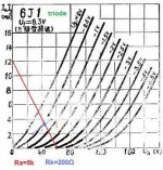
Take the orange tangent line shown at grid = 0V for example. That tangent line crosses 24 mA and 12 mA on the Y axis. The plate voltage at 12 mA is 66 volts and the plate voltage at 24 mA is 108 volts.
Therefore the inverse slope of that tangent line is (108-66V)/(24-12mA) = 3.5k
Therefore the inverse slope of that tangent line is (108-66V)/(24-12mA) = 3.5k
How did you come up with the figures 3.3k and 9k?
_I_ grabbed the orange line and slid one end down to 0V 0mA. Then peeped the V and mA at the other end of the line. Math as the others say; simple division.
This also highlights the fact that rp is NOT a "constant". It is different around every operating point, and for large swings around that point.
The PRR is correct, of course.
rp is variable and depends of the operating point.
Some posters here on tube forum, find that rp is determined by the curve Vg=0 only, and "everything else is the internal resistance of the tube".
I didn't even have the will to discuss with them about it.
rp is variable and depends of the operating point.
Some posters here on tube forum, find that rp is determined by the curve Vg=0 only, and "everything else is the internal resistance of the tube".
I didn't even have the will to discuss with them about it.
OK, here's what I'm trying to figure out . . . a poster on another forum measured voltages in his FX-01 preamp that uses these tubes in triode.Take the orange tangent line shown at grid = 0V for example. That tangent line crosses 24 mA and 12 mA on the Y axis. The plate voltage at 12 mA is 66 volts and the plate voltage at 24 mA is 108 volts.
Therefore the inverse slope of that tangent line is (108-66V)/(24-12mA) = 3.5k
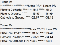
The PS has rails that measure +34v / -34v. He measured 51v plate voltage (plate to cathode). He measured -32.19v cathode to ground with tubes installed and -34.44v cathode to ground with tubes removed. So I figure the cathode is at +2.25v so the grid is at -2.25v.
Looking at the curves, that operating point doesn't even seem to be on the chart. Or maybe it's super close to the X axis?
Working off the -2v curve I get: (60v - 45v) / (0.8ma - 0ma) = 18.75k
Am I doing it correctly? I'm confused because the cathode resistor is 200 ohms and that would indicate (2.25v / 200) a current of 11.25mA.
I am going to speculate that the "-34V" is not stable when tubes are removed, and changes a lot more than just "200 Ohms".
Just another 300r of rail impedance leads to a more likely operating point.
Knowledge of the plate resistor would give a better estimate of the working current.
Running simple tube circuits on +/- power, IMHO, should be banned. It has no advantage, just confusion. (There are more elaborate systems where it makes much sense.)
How much did the negative rail move when the tubes were removed? You cannot measure voltage on tube electrodes by removing the tubes.FlaCharlie said:He measured -32.19v cathode to ground with tubes installed and -34.44v cathode to ground with tubes removed. So I figure the cathode is at +2.25v so the grid is at -2.25v.
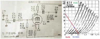
Yes, I believe that schematic is what the various versions of these little preamps use.Probably something like this inside.
Mona
The power supplies are apparently different, though, with some requiring an AC input voltage and some DC. The one that was measured uses DC input from a linear supply. As I said, the +34v / - 34v were measured with a PS that supplied 13.3vdc which is the input that resulted in a heater voltage of 6.3v.
Here's a version that uses AC input. Same signal schematic and more readable. I don't understand these types of PS and really have no interest in that part of the circuit.
I've been breadboarding a simple, single triode, preamp design with a variety of tubes and since the owners of these rave about them I thought I'd try them.
Since I'm using a more traditional tube PS I asked someone to measure the actual voltages so I can listen to the circuit in "stock" form. Am I correct that a B+ of 68v would produce the same operating point?
I don't own one of these FX preamps so I'm relying on measurements taken by someone else and I doubt he wants to pull it apart again to do more measurements. Here are the voltages he posted. I'm not sure why he took readings without the tubes in place.I am going to speculate that the "-34V" is not stable when tubes are removed, and changes a lot more than just "200 Ohms".
Just another 300r of rail impedance leads to a more likely operating point.
Knowledge of the plate resistor would give a better estimate of the working current.
Running simple tube circuits on +/- power, IMHO, should be banned. It has no advantage, just confusion. (There are more elaborate systems where it makes much sense.)
As the schematic shows, the signal portion of the circuit uses a 4.7k plate load and a 200 ohm cathode resistor. My interpretation of his readings led me to extrapolate a B+ of 68v and a cathode voltage of 2.25v. Maybe I'm seeing it wrong?
As I said, I have no understanding of this type of PS and really have no interest since I'll be breadboarding it with either an adjustable bench supply or a traditional CLCRC PS if I can scrounge up a suitable PT.
Why would the negative voltage rail fluctuate?
Attachments

It is amazing what some people will buy/build for audio. That circuit adds PSU hum/ripple/noise from the negative rail straight into the incoming signal. Then it amplifies the signal by probably too much and outputs with a somewhat too high impedance.
The negative rail will change when the current drawn by the circuit changes. To check the bias conditions you need to measure the voltage across the cathode resistor. You seem to have every other voltage apart from the one you actually need.
The negative rail will change when the current drawn by the circuit changes. To check the bias conditions you need to measure the voltage across the cathode resistor. You seem to have every other voltage apart from the one you actually need.
You are right, i took the 80 for a 60, it's a horrible copy
.
Mona
So, when a 2V sinus steers the grid direction grid current its upper top gets flattened out (causing H2), and when it steers direction cut-of its bottom flattens out (causing odd harmonics)? Or is this put to simple?
Anything decent would call for a 100V PS and a 7K 8K load I guess. But that would probably give too much amplification.
It is amazing what some people will buy/build for audio. That circuit adds PSU hum/ripple/noise from the negative rail straight into the incoming signal. Then it amplifies the signal by probably too much and outputs with a somewhat too high impedance. The negative rail will change when the current drawn by the circuit changes.
Yeah, the PS in the schematic is not what the FX uses. The PS that FX ships with the preamp is a wall wart SMPS that supplies 12.33 vdc unloaded. The PS that resulted in the +34v / - 34v readings was an adjustable linear supply set at 13.3vdc unloaded and I believe it is a regulated supply. If it's regulated the negative rail should be stable, no?As far as i know the FX-01 uses a simple SMPS to get the + and -34V.
Mona
My interest is just duplicating the level of voltage with a standard PS. I figured 68v B+. Is that correct?
I figure if I breadboard it with the correct B+ and the same value plate load (4.7k) and cathode resistor (200 ohms) I'll be able to measure it myself.To check the bias conditions you need to measure the voltage across the cathode resistor. You seem to have every other voltage apart from the one you actually need.
That said, doesn't the schematic seem to indicate 2.25v from cathode to ground?
I figure with tubes out there would be no current, so no drop across the 200 ohm resistor. If the resistor was connected to ground you would expect 0v but since it's connected to the negative rail it measures -34.44. With the tubes installed and drawing current it measures -32.19, which is 2.25v higher (more positive). Perhaps my thinking is flawed, though.
If that's accurate it puts the operating point at a somewhat ridiculous point on the graph.
- Home
- Amplifiers
- Tubes / Valves
- 6AK5 in Triode - Plate Resistance?