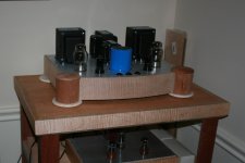
Back in 2007 - long before I was a forum member - I built this amp. I took great pains to follow the schematic exactly, primarily because it was only my second build (my first was from the same author, a 12V6/12SL7 UL PP that sounded wonderful). The only change I made was to use the Hammond 1628SEA OPTs, as they'd just become available at the time and I wanted to avoid the weird frequency response characteristics of the original 1628SE.
I'll cut to the chase here; to say that I was underwhelmed with the sound of this thing would be the understatement of the century. The highs were muddy (at least when compared to my first amp), and what little bass it possessed was flabby enough to incur the wrath of Richard Simmons. I really, really tried to like this amp, being as it was the fruit of my hands and all, but I was ultimately disgusted no matter what I tried - and I tried everything. To this day it remains the only non-breadboarded amp I've ever built and dismantled.
So... now that I have the urge to attempt another SE 6550 (probably a scratch-built Tubelab SSE), I thought I'd revisit my old build to try and learn from my mistake - in this case, blindly building without a better understanding of the design.
The first thing I noticed is that most two-stage SE 6550/KT88 amps use a different driver tube. I suspect that a single 6SN7/6J7 stage might not have the "oomph" needed to get the most out of the outputs using a 2V input signal. I'll cut to the chase here; to say that I was underwhelmed with the sound of this thing would be the understatement of the century. The highs were muddy (at least when compared to my first amp), and what little bass it possessed was flabby enough to incur the wrath of Richard Simmons. I really, really tried to like this amp, being as it was the fruit of my hands and all, but I was ultimately disgusted no matter what I tried - and I tried everything. To this day it remains the only non-breadboarded amp I've ever built and dismantled.
So... now that I have the urge to attempt another SE 6550 (probably a scratch-built Tubelab SSE), I thought I'd revisit my old build to try and learn from my mistake - in this case, blindly building without a better understanding of the design.
The 335V B+ for the output tubes seems a bit low. And the 280V on the driver plates probably doesn't do wonders for the voltage swing, either. Extending tube life was obviously a design goal (understandable given the author's desire to use NOS tubes), but it seems to me that it could've been accomplished even if more efficient (or linear) operating points had been selected.
The DC heater supply is a nice touch, but is probably overkill for tubes designed to operate quietly on AC. And I won't go within 100 miles of the whole cathode stripping debate. To each his own.
Please bear in mind this isn't intended to be an indictment of the design or the designer (he's happy with it, after all), but more of a sanity check. This particular schematic differs from most similar designs I've seen since, and as such I suspect that it contains a combination of design compromises that just didn't suit my taste.
So... am I off base in my thinking? Has my butter slipped off my noodles? Has the cheese been knocked from my cracker? Enquiring minds want to know. 😀
Alas, we hardly knew ye...
Attachments
Here's a link to a 6550 SE kit that I built several years ago. It uses a 6N1P for driver, and it will also run KT88 or EL34, but the 6550's that I use are my favorite. It is (conservatively) 6-8 Watts in triode mode, and 11-13 Watts in UL. Doesn't sound like a lot, but I find it's plenty loud and does a nice job. I really like it.
I believe all of the kits sold out during the first year, but if you look through the thread, you'll find schematic and parts list. I got the basic kit and sourced my own iron and tubes.
KT88 SE Basic or Master Kit
Here's a picture of my build from Post #59 of that thread on the link below.
http://www.diyaudio.com/forums/atta...7635-kt88-se-basic-master-kit-amp_running-jpg
Last edited:
To my eye, the standout detail is the 20K load on the front triode. That's quite low. Echoed by the relatively large cathode resistor, 6.8K. Normally these two are a ratio "like" Mu, which for these tubes is ~~20; here we find a ratio of 3.
This puts triode plate way-way up at 86% of the B+. In a "fair fight" we would aim for 50% for maximum both-ways swing. We can't set up a "fair fight" with tubes, but the 50%-70% range is popular for large signal swing.
Designing with blunt rocks: We want RP (plate resistor) 2X to 5X rp (plate resistance), and RL (load) 2X to 5X RP. Working forward from 12AU7's ~7K rp, we pick RP as 14K to 35K. Working backward from 270K grid resistor, we pick RP as 135K to 54K. Quite a spread, which implies 12AU7 should have NO trouble driving 270K. Take the middle and grab 47K blunt-guess.
Or-- GE didn't get rich by giving bad advice. GE sheet has R-C Amplifier suggestions. For 300V and 240K (their "Rs") load they liked 100K or 240K! Since 6550 grid capacitance may droop below 270K by 20KHz we lean to the lower 100K RP, and they liked 4,400 Ohms as the cathode bias. Max output at 5% THD is 41V RMS, 57V peak, comfortably in excess of the 28V apparently needed on the 6550.
This is still 3% THD at 6550 clip point. I don't care to plot what it may be with the much heavier 20K loading starved for current.
Or speculate why R3 is there. It pulls-out DC voltage and adds AC load so the triode sees 19K to 312V. And this with the apparent 280V at plate means even if the triode cuts hard-OFF it can only swing up 32V. We need 28V, gain drops as we try to reach cut-off, the linearity seems to be awful.
"Some" nonlinearity in the triode will cancel the nonlinearity in the power stage. As the triode is struggling to cut off, the pentode is swinging into a happy high-gain zone. But that triode is in real trouble. A point: this thing won't go into grid-blocking and fart-out on overdrive. But going-sour is not IMHO the better alternative.
I would try 100K RP with 4.7K RK; or all respect to GE, 47K with 2.2k. These will give way-more than 28V swing with the sort of small smooth nonlinearity that will cancel power bottle nonlinearity well.
Loading: this thing can't really approach 6 Watts, which is shameful for a 42W bottle. The "20W" number in the 6550 suggestions is for gross THD and large bias-shift and may not even be guitar-quality; it may be good for 400Hz servo-motor drive. Realistically you can get 13W clean and 17W @>5%THD as pentode, some less as UL. But as you say, the supply voltage is low for a 5K load. 13W in 5K is 255V RMS or 367V peak, plus pentode/UL drop, points to well over 400V supply. (I ran close to 600V with 10K load on my last solo 6550.)
Taking another blunt-rock approach: 350V available in 5K DC equivalent is 70mA. This is a piddly 25 Watts; I had no trouble with 6550 at 39W-41W; but more is not going to be much more output. I might slide toward 80mA to reduce nonlinearity on the downswing. 28W is very conservative for 6550. 10W out is not too shabby. Especially if not lamed by driver limits.
The DC heater supply is notable in that it has 0.2V ripple and no ground reference. As you say, ordinary wiring can do well especially with NFB. I see no point in DC heating power tubes with massive audio swings. Guitar amps are just-tolerable with AC heat at levels 1,000X lower. DC heat on the triode may be a frill to try, after the base amp is happy.
I've built two SE 6550 amplifiers - one using an EF86 pentode driver RC coupled to a 6550 in UL. 450VDC for the output tube plates. Big Hammond output iron. Originally used EL156s but switched to 6550s due to the so-so quality of the Chinese EL156 version. Loop feedback. Very powerful sounding amp that had no problem driving a pair of UREI 813A speakers.
Another design was a 5687 dc coupled to another 5687 which in turn drove a KT88/6550 in pentode mode. 400VDC on the plate. Loop feedback. Used James iron which didn't have the same low frequency response as the Hammond but was still good enough for rock music.
My latest design - not quite 6550 - but in the same vein is a pair of 1625s in parallel single-ended. 425VDC on the plates. Hammond 1627SEA output transformer, 12HG7 pentode driver, plate-to-plate feedback. I'm still debugging one of the monoblocks - been too busy to dive into it to figure out where I messed up!
Member
Joined 2009
Paid Member
The photo of the amp looks great - definitely worth rescuing. In addition to the great advice on operating points, maybe worth posting the psu design for review too.
Ugh, yeah, that driver stage isn't well designed, but you don't need a different tube, just a competent design.
R3 serves no good purpose, toss it. R4 should be at least 47K, maybe more. R2 will need to shrink to drop the bias voltage a bit. If you need help working up a load line, just let us know.
On the output side, I would recommend either triode strapping the output stage, employing feedback, or wiring as a pentode and adding feedback. UL without GNFB is likely what you're hearing down low that you don't like. Hammond single ended output transformers aren't likely to support much feedback, so I'd recommend trying triode strapping first. Otherwise, Kstagger has pointed out that you can use plate to plate feedback to achieve your goals without running into output transformer induced instability.
I hate that this amp is DC heated. For one thing, you're not giving anything up by using AC heating. #2, the heater winding/DC supply has no reference to ground (a big no no). #3, the winding is rated for 6A AC, you will draw more AC current than this heating two 6550s and two 6J5s with a cap input bridge rectifier.
You can also dump the HV relay circuit. It's superfluous at best. The presence of S2 also annoys me.
R3 needs to go away, no reason to be there that makes any sense.
The standby(?) switch and relay arrangement is unnecessary for all intents and purposes.
DC heaters are also unnecessary and just added heat to go from AC to DC with the rectification, especially if you aren't bothering to regulate them. Simply tightly twist the wiring and route it correctly and it should be nice an silent.
I would at least double the capacitance at the output tubes cathode as well.
Part of me would be inclined to lose the bypass cap and go to a higher mu input tube, like the 6N1P, 6DJ8/6922, or similar, and run a smidge of global negative feedback, but that's just me. Otherwise it might be more linear as a straight triode connection without some global.
Thanks for all the feedback, fellas. And to Bigun's post, I did indeed save the chassis, output iron, and all the other "goodies". Unfortunately, two of the marble coasters I used for "feet" were broken during a recent move, but they're easily replaced.
So this whole thing started last week when I got the itch to build another SE amplifier. I've thoroughly enjoyed my little RH84 (love it or hate it) for nine years now, but it's time for system update. I've admired George's (er, Tubelab's) designs for some time, so I finally decided to drop the hammer and do a point-to-point build of a Simple SE (note that I do intend to purchase one of his boards, however; he deserves the support).
But my dissatisfaction with that original SE build haunted me: why didn't I like it? Was it me, the design, or both? It was time to find out - hence this post. I wanted to see if I'd learned enough over the past decade or so to develop that sixth sense of "something doesn't look right".
BTW thanks to PRR for that in-depth look. I thoroughly intend to run the numbers later this week, and you've given me several places to start.
What didn't worked, very simple.
1. The tube, hard to get a low distortion middle ground, even harder to make it work both UL or 'triode'
2. Look at the 300B, way better tube.
3. You said it: driver inadequate, as soon as there is grid current the driver is dead.
4. Not enough gain, no feedback, impossible to drive normal speakers or achieve good THD, result in no bass, mix-up sound.
Solution: NOTE: I don't build S.E.T. yet because of the difficulty of the design/cost ratio.
1. Drive the triode tube with a cathode follower, like two sections of the 6sn7.
2. Use global feedback.
3. Use pentode gain stage to max it out.
4. Transformer quality matters if you build S.E.T, Hammond might not be enough, (very basic transformer).
5. Use Grid bias to maximize the power output.
6. Bias the cathode follower , Bias the triode Cathode, Monitor both voltages, Maintain bias through Cathode follower feedback monitor bias to ensure constant current in the triode.
7. You will be able to drive the Triode output into Class B no problem for double the power.
As example: 300B with no feedback averages 1.5% distortion at 1 Watt, and 10%at like 10 Watts. 300B with feedback can achieve 1% or little less at 1 Watt. 300B with feedback with Class B constant bias with regulated supply, and grid bias, achieves over 10 Watts with 1% THD with better sound. Same principle applies to a 6550 tube, however it is even more complicated 🙁
Member
Joined 2009
Paid Member
I've heard very good sound using Hammond iron, for the most part I don't see it as a limiting factor here. Even the entry level Hammond iron is capable of good sound (Don Garber has used the 125ESE).
The Wimpy driver argument is another item I would challenge. You don't need to operate the power tube anywhere near grid current. Most people with a 300B don't do that either. The issue is having enough slew rate to avoid treble roll-off due to Miller capacitance. I don't know how much Miller the 6550 has but drive requirement can be calculated. Even with treble roll-off, it doesn't mean it would sound bad but if the slewing is really limited it will produce distortion. I agree with PRR that there's some things to look at with the operating points.
No use driving the triode into Class B - as a single ended amp, Class B is not an option.
I've attached the 6550 Triode Curves (from Turner Audio). They look pretty good to me. In Triode mode you essentially have local feedback linearizing the tube so you'll get less gain from it and less output power but lower distortion. Many people report preferring the sound of Triode mode to UL mode - let your ears decide.
Attachments
Last edited:
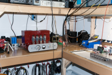
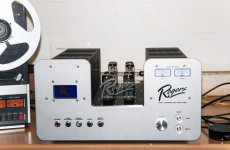
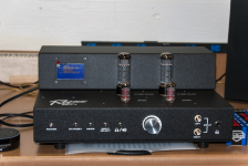
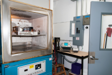
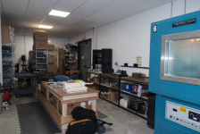
Speaking of Hammond transformers, this month's meeting of the NJAS was at Rogers High Fidelity in Warwick, NY. I noticed some Hammond iron on some units they were developing and testing in the Thermotron. So I mentioned to Roger Gibboni himself that Hammond iron was not always considered top shelf by some in the DIY community and wondered if he had heard of that. His reply was no and that his transformers being made by Hammond were not off the shelf units. In fact he said that "you could not buy a transformer from Hammond that were the same as he uses". (I also saw Edcor's in the shop as well.) I accepted his reply, of course, but wondered to myself just how different (if any) they really were, skeptic that I am. Below are pictures from the shop and listening room.I've heard very good sound using Hammond iron, for the most part I don't see it as a limiting factor here. Even the entry level Hammond iron is capable of good sound (Don Garber has used the 125ESE).
Attachments

Member
Joined 2009
Paid Member
Adding the 5k loadline onto the triode curves for the 6550 shows what it might do (into an ideal load) and for my thinking it doesn't look too bad at all (but clearly not using the power the tube is capable of, for which you want more B+). A triode output is worth trying.
The driver should be improved. I did a bit of looking around and thought it would be great if you could keep an Octal tube as it saves messing with the chassis and it preserves the look you have achieved. My thought is to try the 6AC7 (not the 6CA7!) which is a highish transconductance pentode. Pentodes do much better into relatively low load resistances than do triodes in terms of distortion (try 10k).
I would tend to stay away from using feedback simply because it's an added complication in term of stability, especially if the amp was not laid out with that in mind.
Attachments
Last edited:
Doubling up on what others said, operating a 6SN7 / 6J5 with 6.8k cathode resistor, and
20k (and the extraneous parallel with 470k) is not good.
~ 1.8 mA through a 6SN7 / 6J5 is starving it to death. No matter what follows in the output stage, I would not expect that driver setup to sound good.
You do not have 500V B+, so you can not run the 6SN7s with 25k Ohm plate loads, and 1k Ohm or 820 Ohm cathode resistors.
So, instead use an 820 Ohm cathode resistor (with bypass cap, of course), and use an IXYS plate current source set to 8 or 9mA.
I use AC filaments on two stage SE amplifiers with Triode driver u (mu) of 17 up to 44, and Pentode / Beam Power output tubes in Triode wired mode, and have less than 500uV hum < 0.5mV).
I use medium efficiency speakers, and do Not listen to headphones. AC filament Hum is not a problem for me.
Ultra Linear is a form of local negative feedback.
Triode wired is a form of local negative feedback.
They both have less delay than global negative feedback.
Triode wired has about 1/2 the gain, and also about 2 times the damping factor (better), versus:
Ultra Linear which has about 2 times the gain, but 2 times lower (worse) damping factor.
Try Triode wiring, trade off gain for better control of the loudspeaker.
Also, there is Very Little delay in the negative feedback of triode wiring (use a 100 Ohm resistor from screen to plate).
Ultra Linear does have delay in the negative feedback as a result of the leakage inductance from the plate winding portion, to the ultra linear winding portion. It is dependent on the quality of the output transformer.
I would have checked the coupling cap, maybe wrong value?
The 20K ohm is weird.
Then compare to another se with a 6j5
6V6 6J5 Class A Vacuum Tube (Valve) Amplifier Circuit | Electronic Circuits
But you've dismantled it.
Hammond OT's ,
I'm using the Hammond 125ESE in this,
"Analog Circuit"
It took months for the sound to improve, I really like it.
more
Tom Schlangen's Homepage - Tube DIY Pages
Tom Schlangen's Homepage - Tube DIY Pages
Norwegian Wood
see post#10
SE EL34 schematic HELP: from two 6SL7's to One?
Hammond 125e Universal lots of options, works fine (the ugly one everyone disses- I've got them on my breadboard amp)
Don Garber Fi X
http://www.enjoythemusic.com/magazine/equipment/1212/garber_fi_x4.htm
http://www.dogstar.dantimax.dk/tubestuf/gallery3.htm
I have no experience with the Hammond Sea, and didn't build yet the Set amp. However I have at least 3 schematics ready (soviet tube, 845, parallel 300b which needs refinement) and sourced a few more from excellent companies, intensively researching all the topologies, specs and benefits vs price.
I just want to clarify how I see UL, triode, pentode etc.
In UL you have more gain and the pentode curves into a triode form. It is in the middle ground between a pentode and a triode.
The advantage of UL is to greatly reduce transformer distortion which enable a lower quality of winding/core, still the transformer UL winding and size is very important.
If you use the triode configuration you will get 100% of Output transformer distortions and reduced bandwidth. The only way to correct it is to inject a lot of GNF.
In UL, you already start with the advantage of gain, but you still need lot of GNF to reduce the output resistance, the UL has a higher output resistance than the triode.
For small tubes, UL is a clear winner, for middle power tubes like 6550, UL or Triode is fine but each has downsides and advantages. For high power Pentodes Triode is clearly the way to use them, they have also higher internal Rp.
This is the typical response you get from manufacturers who get caught using Hammond iron.His reply was no and that his transformers being made by Hammond were not off the shelf units. In fact he said that "you could not buy a transformer from Hammond that were the same as he uses".
Bwaaaa-ha-haaaa! Kinda' like the dirty old man who says, "I only read Playboy for the articles". Or perhaps more fitting: "Pay no attention to the man behind the curtain!" 😉
I know some of the folks on the forum like to cover their transformers, and that's okay. But I'm always a bit suspicious whenever I see a manufacturer do that. I don't have a problem with it as long as it's obvious that the product is being built to a certain price point using budget iron. It's when cheap stuff is being pawned off as "potted" iron that I get apprehensive. Some of the Asian vendors are really bad about that. BTW it's worth noting that Lundahl sells covers for their transformers, but they're done right - with mounting and ventilation properly accounted for.
Now back to our regularly scheduled program...
That now-dismantled SE amp was my only experience with Hammond output iron, so I can't really call myself any sort of authority on their overall sound or finish qualities. But my "gut" told me that the problem with that amp lay within the circuit itself rather than the OPTs. I do know that George (Tubelab) did some comparisons between Hammond and Edcor OPTs, and pretty much concluded that they are what they are. In other words, they ain't Tango, but they'll certainly do.
Member
Joined 2009
Paid Member
I've heard a SET amp based on SV811-3 playing through Hammond iron and it was something special to my ears. I have a Sowter OPT to try out sometime, that will be interesting.
Hammond will custom wound the transformers with any interlayers as needed, with techniques as specified if ordered enough. Also their transformers are very good.
In the E core market it is all trade-offs, however dynacos are awesome.
For serious design please look at least at a C core, double C core, toroid or R-core, they all have better electrical properties. The only thing E core excels at is loosing the signal and wasting electrical fields. R core and Toroid's needs to have tiny slice out and re-joined with some glue.
E core = cheap to produce, basic, C core better, double C core better, than Toroids and R-Core are another thing = controlling bias in class AB is critical to prevent saturating the cores.
- Status
- Not open for further replies.
- Home
- Amplifiers
- Tubes / Valves
- 6550 SE Amp, Revisited