1) Try using fixed bias for the 6550 instead of cathode bias.
2) Run the 6550 like the data sheet suggests in pentode mode: 400 volts on plate and 225 REGULATED volts on G2. Use 3 0A3 regulator tubes in series ( or other VR tube combination) to get the regulated 225 volts for G2.
3) Improve driver as mentioned above.
This will give you an amp that will sound more to your liking.
Yes , if you want the best , pentode all the way with lots of feedback,
use to the max the tube potential, regulate G2, finally someone makes sense.
danFrank we should design our S.E.T. together haha
use to the max the tube potential, regulate G2, finally someone makes sense.
danFrank we should design our S.E.T. together haha
HMMM this looks like a clone.
look at the ckt on p 81 of 143, the Audio Express diagram looks wrong, see the 470 k resistor
http://www.criticalradio.com/Ham Stuff/143 Tube Amplifier Schematics WW.pdf
L63=6J5
L63 @ The Valve Museum
This wouldn't be the only time Audioxpress screwed up. They had a 25L6 se amp with a resistor tied to the wrong side of a cap.
Last edited:
Excellent eye! You know, I'd have to rebuild the circuit to see if that 470k resistor was the culprit. But to me it's just not worth the effort; there are much better designs out there with a similar topology.
It gets more interesting. Remember that first amp I mentioned? Compare it to the 6V6 design below from an old 1950's Acrosound catalog. It appears in both cases the author retained the original circuit almost verbatim, with an updated power supply and only minor changes to the circuit - mainly 12V cognates and/or slightly different driver tubes. In hindsight, each one of those builds would've been a more enriching experience if it had been more apparent these were updates of proven designs (again, not an indictment, but I wasn't an "old-timer" in the hobby at the time).
Boy, do I feel like a stooge.
That 12V6 amplifier sounded incredible though. I used OPTs from an old Heathkit AA-151 my brother found buried in an old junkyard. I wound up giving it to him as a gift years later.
Attachments
Last edited:
Member
Joined 2009
Paid Member
Yes , if you want the best , pentode all the way with lots of feedback...
This is indeed the approach taken inside the Shindo Cortese F2a which uses a triode-pentode driver and a big honking pentode at the output. And it's an amplifier with an excellent reputation. Pitty that the F2a is such a rare and expensive tube but no reason not expect excellent results with other well made power pentodes.
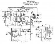
6V6
I built this 6v6 pp amplifier (minus the power supply- I built a regulated power supply)
"Quality Amplifier for TV Sound" p44 of 172
http://www.americanradiohistory.com/Archive-Radio-News/50s/Radio-News-1951-05.pdf
It's got the Stancor Universal A-3830 ot specified in the article.
* I thought this ckt was interesting due to the amount of caps in the amplifier circuit.*
They are on pages 808 & 809 in the Tubes photo gallery
Post #24 schematic:
This is why I do not like "serial phase splitting" (or whatever it is named). The second grid (bottom grid in the schematic) of the 12AX7 is driven by 470k and 510k in parallel.
I estimate the gain of the 12AX7 triodes at about 50. The plate to grid capacitance is about 1.5pF, and with the miller effect, about 75pF. The 470k and 510k resistors and the 75 pf has a -3dB bandwidth of about 8.5 kHz (on the second 12AX7 grid).
That means for frequencies at and above 8.5kHz, the amp is effectively Single Ended. Negative feedback does not fix that. The lower grid is always driven by -3 dB at 8.5kHz (and worse as frequencies go above that).
.... -3dB bandwidth of about 8.5 kHz...
Negative feedback does not fix that. The lower grid is always driven by -3 dB at 8.5kHz...
NFB does fix that. Simmed twice. Both use gain of -50. Once with your 75pFd grid to ground, then to be sure a rounded-up 2pFd in the Miller position. Response is -3dB beyond 100KHz.
An alternate interpretation is that the 1.5pFd is in the same place as the 510K. 1.5p against 510K is 208KHz.
(I did re-run it with 39K series added to the outputs to emulate a 12AX7 plate circuit impedance. No change to 2 decimal places so I did not re-capture the plot.)
Attachments
PRR,
Nice simulation.
There is also the phase lag, at the -1 dB point of 100kHz, it would be about 26 degrees (26 + 180 degrees = 206 degrees). I did not calculate what it would be at 10 or 20kHz, it might be significant or not, as the 'lagged stage' drives the one output tube. I do know when I used a serial splitter, I could see the signals were not 180 phase to each other at the upper end of the audio range.
Yes, the global negative feedback does fix the frequency response of the tube amp. However it has to also 'try' and correct for the unequal drive to the two output tubes (the 2nd harmonic of one, the lack of 2nd harmonic in the other). This "series" splitter causes the 2nd harmonic distortion to be cancelled in the second tube because of the opposite phase of that 2nd harmonic. +2nd + (-2nd) = no 2nd harmonic out of the second tube (we rely on that for push pull to work; but now it is working against us).
But that means that one output tube is driven by a signal that has 2nd harmonic, and the other tube is driven by a signal that does not have 2nd harmonic distortion . . .
Correct?
And anything that has distortion that is fixed by negative feedback creates upper order distortion products, as discussed by Crowhurst, right?
Think of what happens when both outputs are driven with signals of different characteristics.
Then think of what happens when the output stage is no longer in class A, but is in class AB.
When one output tube is the only one on, it is driven by signal with 2nd harmonic.
When the other output tube is the only one on, it is driven by signal with No 2nd harmonic.
It seems to me that 'serial splitters' are not the most linear, nor the most balanced in frequency, phase, or distortion of the various splitter methods.
Last edited:
Member
Joined 2009
Paid Member
It seems to me that 'serial splitters' are not the most linear, nor the most balanced in frequency, phase, or distortion of the various splitter methods.
I agree - their use seems only to have been justified on the grounds of providing gain. However, ARC uses a SS splitter based on this approach and their reference series amps are reckoned to be superb.
common term for the 'serial splitter' is Paraphrase New Phase Splitter
...It seems to me that 'serial splitters' are not the most linear, nor the most balanced in frequency, phase, or distortion of the various splitter methods.
I don't say the floating paraphase is the "most" of anything.
I don't think there is a "best" of any of them. Much depends on implementation.
This is an "improved" Phase Inverter. You sell a one 2A3 or 6F6 radio at $99. You want to sell a two-big-bottle amp at $199, Aside from more cabinet, you need the push-pull drive. At the time, magazines and catalogs were calling transformers old-fashioned. Throwing in an inverter gets the job done and the product out to stores. The classic is a 470K:15K divider in the top output gridleak feeding a gain triode to smack the second side. Of course the divide-down gain-up never works out to unity. The 510K:470K scheme does better with tubes of varying gain. Yeah, it does distort twice; nearly all P-P drivers do somewhere.
- Status
- Not open for further replies.
- Home
- Amplifiers
- Tubes / Valves
- 6550 SE Amp, Revisited