Hi FdW,
Unless you want to takle this all by yourself, it is fine and we wait on your results, but many of us use simulators. That is one aspect of the equation. Simulators are just that simulators, it asumes perfect conditions, pure capacitors and resistors, things are perfectly matched. In other words the perfect world.
Keep this in mind before getting to extatic about the numbers presented in the FFT.
Have fun I am keen to see what comes out of this.
Nico
For now, I will try this on myself, I will publish the graphs and the simulator settings, and hope for comments on how to improve the settings.
And 'Simulators are just that simulators', Nico, I totally agree, and it is also the reason that I was looking for help (on the simulation parameters). The numbers that I am getting are 'too good to be true' and if so should be distrusted.
But it’s all great fun 🙂 and maybe ‘Simulators are stimulators’ also


What is this, a LDA? (low drop amplifier 🙂), rail to rail within 97%
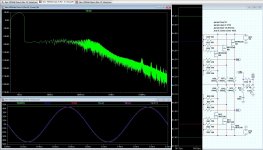
It took some doing, but it has been done, the ‘New class A’ is now running with 6 pairs of IRFP 9240/240’s, the bias current is set to 5.14Amp (857mA per device) good for 105Watt class A. power dissipation in each device is about 39Watt. Later I will show the new performance graphics, but first some absolute maximum values.
The graphics shows the amplifier running at absolute maximum output (there is some distortion showing up due to clipping in the driver stage). V(max) and V(min) on the output connector V(out) are at 43.61Volt (97% of the rail).
At V(pos) +45Volt, V(gen) 2.1752, R(load) 8Ohm
V(rsp) = 44.71Volt
V(nfb) = 43.76Volt
V(out) = 43.61Volt
Attachments
output bias set to 5.14A total.
How do you dissipate 460W (45V * 5.14A * 2) from your sinks?
5.14A bias gives 10.28Apk ClassA output.
105W of ClassA into 8r0 only needs 5.12Apk
210W of ClassA into 4r0 needs 10.25Apk and that is available from your 5.14A bias setting.
How do you dissipate 460W (45V * 5.14A * 2) from your sinks?
5.14A bias gives 10.28Apk ClassA output.
105W of ClassA into 8r0 only needs 5.12Apk
210W of ClassA into 4r0 needs 10.25Apk and that is available from your 5.14A bias setting.
output bias set to 5.14A total.
How do you dissipate 460W (45V * 5.14A * 2) from your sinks?
5.14A bias gives 10.28Apk ClassA output.
105W of ClassA into 8r0 only needs 5.12Apk
210W of ClassA into 4r0 needs 10.25Apk and that is available from your 5.14A bias setting.
The amplifier will not deliver more than the 5.14Amps until it goes into AB witch it will not (42Volt(peak)/8Ohm(load)=5.14Amps).
This is what I am thinking about (see the LA14-300 or LA15-300).
http://www.fischerelektronik.de/fischer/uploadfischerfcool/Fischer/D03_D.pdf
I'm sure they will be pricy
You don't think 5.14A quiescent current of a push-pull amp does +100W Class A continuous output power in 2 Ohm ?
You don't think 5.14A quiescent current of a push-pull amp does +100W Class A continuous output power in 2 Ohm ?
But it will do in 8Ohm 🙂 (5.14*.707)*(5.14*.707)*8 = 105.34Watt(rms).
The simulation shows that the amp will deliver 10+Amps in 4Ohm and I did not test with lower loads, but I am sure (if the power supply will) it will, the Rds value is very low. But then it will be in class AB.
Hi Frank,
I looked at your old construction; it reminds me of the way Quad constructed their 405 amplifier: pretty compact, with bundles of all sorts of wire (signal, power supply...).
When you start constructing your new amp, give it a bit more space, and don't share all wires in bundles for the sake of a good look because there will be quite some capacitive coupling between these wires as long as they are not screened. This is what you don't see when simulating but might be the cause of HF oscillation, hum and so on.
Verslik je niet in de oliebollen!
Hi Frank,
I looked at your old construction; it reminds me of the way Quad constructed their 405 amplifier: pretty compact, with bundles of all sorts of wire (signal, power supply...).
When you start constructing your new amp, give it a bit more space, and don't share all wires in bundles for the sake of a good look because there will be quite some capacitive coupling between these wires as long as they are not screened. This is what you don't see when simulating but might be the cause of HF oscillation, hum and so on.
Verslik je niet in de oliebollen!
Yes I know (both the parallel wires and the 'oliebollen'), thanks 🙂
Member
Joined 2009
Paid Member
Frank - did you ever build this secret amp ? (just saw this thread in recommended related topics whilst browsing the Alpha Nirvana threadj
The current commercial amplifier, see Signature Origin | Home of Signature Quality, is based on a current conveyor design that has not been published here. Maybe one day 🙂

- Home
- Amplifiers
- Solid State
- 63watt class A into 8Ohm, 110watt semi-class A into 8Ohm, @ 20Khz 3rd harmonic -90dB