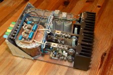
... and 280Watt(RMS) class AB into 4Ohm.
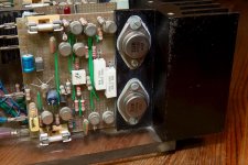
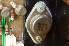
That’s it, this thing sits on my desk for about 30 years now, it may even be the first power HexFet amplifier in the world (for as far that I know), the first version was built about 27 years ago and was designed for IRF HexFet’s (the IRF140). At that time I was an engineer for a Dutch company that was the representative for IR (International Rectifier), the components where very new, the first ever HexFet was being sold in (or around) 1978. But being working for IR gave me access to early samples.
This thing is different, it runs from one supply voltage, + and – 45Volt, and the output goes rail to rail, actually +42 to -42Volt. The topology of the amplifier is differs to any I have ever seen, but I am not 100 percent sure it is my design/invention. Naturally part of the design is conventional and re-usages earlier design principles.
That first version has been my main amplifier for years, it hummed and hissed all the time, but it sounded very ok and it was the only amplifier that I owned.
Last month I did rediscover the build version (later I will post some pictures) and started to dig up those old designs. The next thing that I did was; put the design into a spice program (I used LTspice) and run a few simulations, and it worked.
Now two weeks later I have the design fully optimized en modernized, all components are replaced with modern/current versions. No humming and hissing any more.
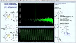
Have a look at the attached picture, it shows the amplifier running (simulated) at 20Volts into 8Ohm at a input frequency of 20Khz, the first significant, and last, harmonic is 30Khz at about -90dB. The graph also shows some spikes at 200/300Khz but I do not think these are significant (any way it’s version beta 0.9).
Let me know what you think about this, and should I show it or sell it 🙂, I do need some advice.
Regards,
Frans de Wit.
Attachments
Last edited:
quote 155Watt semi-class A into 8Ohm .........and the output goes rail to rail, actually +42 to -42Volt
150watt with 40V rails ? I thought it would be less
150watt with 40V rails ? I thought it would be less
I don't think hes gonna publish the schematic since he placed the graphs on top of the circuit.
I'd like to know what settings he used for the fft.
I'd like to know what settings he used for the fft.
Tekko, you can see the settings on the right side of the graph, and I am rely seriously thinking about publishing the schematic, but give me some time to think about it, and maybe someone is going to give me an offer of some kind...
Regards,
Frans.
P.s. one can always hope 🙂
.param a 10K ; step param a list 1K 10K ; Fin
.param b 0.98 ; Vin for 20Volt out
.tran 0 6ms 1ms 10n
Regards,
Frans.
P.s. one can always hope 🙂
.param a 10K ; step param a list 1K 10K ; Fin
.param b 0.98 ; Vin for 20Volt out
.tran 0 6ms 1ms 10n
Last edited:
Tekko, and if you see anything wrong with the settings I will rerun using different ones (as I indicated, it is the first time I am seriously using a spice tool (of any kind)).
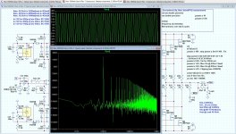
Here is another picture, the amplifier is running into clipping at 42Volt delivering about 155Watt RMS into 8Ohm the output stage is never out of current (does not enter class AB). The first harmonic 20Khz is at -60dB. Pretty cool for an amp running into clipping 🙂
Regards,
Frans.
Regards,
Frans.
Attachments
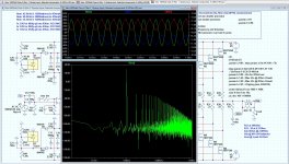
One more picture 42Volt 155Watt, this is showing the source current, and you can see that the amplifier is at clipping point, the positive side just running out of current… (red and blue traces)
Regards,
Frans
Regards,
Frans
Attachments
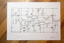
First of all, let me add the original (1982/83 or there about) schema (do not try to build this, it is rubbish 🙂) but the principle works.
Attachments
Last edited:
> (42*.707 * 42*.707)/8 = ~ 100watts
Stupid me 😱
not (V*V)/8/sqrt(2)
but (V/sqrt(2))*(V/sqrt(2))/8
I will change that 😱
Even the file names on the posted pictures do read 100Watt... I think it's some form of a blackout...
Warning: For all reading this, all Watt-numbers given before this message must be divided by 0.707 🙂 except the numbers given by tinitus and multisync. (see also Audio power - Wikipedia, the free encyclopedia).
Last edited:
tinitus,
The amp runs idle at 4Amp (not the hand written schema and the pictured one, that was running at 1Amp nearly never in class A) with 2 current sources of each 4Amps (the new amp), total idle dissipation is 4*90 = 360Watts. Due to the 2 current sources it operates somewhat different than other amps. If you treat it like a SE amp it does ((4*.707)(4*.707))*8 = 63Watts class A. But before the amp goes into AB it delivers about 100Watts, it then cannot go into AB due to the power supply of 45Volt. This is different for a 4Ohms load it will then go into AB when the 4Amps run out, it will still deliver about 40Volts into 4Ohm. Before the current sources go into current limiting, they will deliver about 10Amps.
Regards,
Frans.
Last edited:
155W into 8r0 requires 49.8Vpk and 6.2Apk.The rail is 45Volt, and (42*42/8)/sqrt(2) = 155
You can't get that from +-45Vdc supply rails.
what temperature are the heatsinks when dissipating 360W?The amp runs idle at 4Amp .............. with 2 current sources of each 4Amps (the new amp), total idle dissipation is 4*90 = 360Watts
What is Tc of the mosFETs when dissipating 90W each?
What is the maximum power that a(n overheated) mosFET can deliver?
155W into 8r0 requires 49.8Vpk and 6.2Apk.
You can't get that from +-45Vdc supply rails.
My mistake AndrewT, that is what you get if you write a little macro and trust it without further checking. The number should be 110Watt. (see msg #13, http://www.diyaudio.com/forums/soli...hm-20khz-3rd-harmonic-90db-2.html#post2412135)
Last edited:
- Home
- Amplifiers
- Solid State
- 63watt class A into 8Ohm, 110watt semi-class A into 8Ohm, @ 20Khz 3rd harmonic -90dB
