Just noticed the transformer voltage.................
My AC primarys are 55-0-55 so I should be hitting 250W-ish which I want to double into 4ohm............
Max smoothing capacitor voltage will be above 80V. You will have to use 100V capacitors.
Expect supply rails to be around ±75Vdc to ±87Vdc depending on mains voltage and output current.
A channel delivering full power after the supply has sagged to around 75Vdc should put out a maximum voltage of 70Vpk if you design the system well and maybe only 65Vpk if not designed so well.
A single channel driven to maximum will not pull the PSU down as low and could put out a maximum voltage as high as 75Vpk
Pmax = Vpk²/Rload/2 and for 65Vpk comes to 264W into 8ohms. 4pair of robust transistors can meet this.
But for a single channel driven hard, 75Vpk would be way over what a 4pair stage can reliably manage into 8ohms unless you use 250W To3 devices. Or 4pr mjl4302/4281 on a big cool heatsink.
Forget about using a 4ohms load with a 55-0-55Vac transformer, unless you go to ClassG or H
Last edited:
Hi Andrew,
I have that covered, all caps are 100V. How did you reach 87? I get ±84V though there isn't much in it. I don't know how good the regulation is on this huge transformer under one channel fully loaded, something I was thinking about testing.
This 4 ohm spec is more about the amp's ability to handle difficult 8 ohm nominal loads competently, rather than drive 6, 4 ohm speakers which isn't something I'd want to use it for. I might wish to bridge channels 1,2 3,4 though but I'm thinking about dropping this if the amp I choose puts out over 300W into 8 ohm on nominal mains voltage. My 703 speakers are horrible dropping to as low as 3 ohms.
I might increase the number of transistors for just the first 4 channels with maybe only 5 pairs for channels 5 and 6 for the ability of driving difficult 8 ohm speakers properly?
Does anyone have any comments on the big architecture drawing?
Last edited:
Another idea that could potentially save on transistors would be to design for a tighter mains tolerance and have a warning light come, with the implication that the amp cannot be used for 4 ohm nominal loads when exceeded.
Maximum output voltage = 253/230*110*1.03 = 124.63Vac
times sqrt(2) gives 176.2Vpk
subtract a single diode per polarity gives ±87.4Vdc
if you have a bridge rectifier on each winding, then subtract two diode drops from each polarity, giving a maximum of ~ 86.7Vdc
Will your special rectifier drop less, or more, volts when passing significant currents?
Specifying 4ohms instead of 8ohms is not the way to assess suitability for a severe reactance 8ohms speaker.
Instead do a temperature de-rated SOAR using maybe 60degree phase angle and allowing for 100ms as permitted loads for intermittant transient peaks.
The divide by 5, I gave earlier already takes that into account for many BJT types, if the heatsink temp is kept reasonable.
Last edited:
Hi Andrew,
My calculation is all the same except for the 1.03 added in, what is this from? I think the SCR's pretty much exhibit typical diode behavior when fully "on" for 180 degrees.
I'm going to see what AC RMS voltage I have for a one channel load on the transformer before I decide what to do about 4 ohms.
A big transformer is normally more efficient and lower regulation than smaller.
I guessed at a regulation of 3% for your very big toroid.
Bridged into 8ohms will be just as bad as driving 4ohms.
I guessed at a regulation of 3% for your very big toroid.
Bridged into 8ohms will be just as bad as driving 4ohms.
Tested the transformer tonight
243.5 --> 61.3 unloaded
241.0 --> 60.0 loaded @ 700W
I have some thinking about what to do next.
Wish I could lower the secondary output by 5 volts or so...
243.5 --> 61.3 unloaded
241.0 --> 60.0 loaded @ 700W
I have some thinking about what to do next.
Wish I could lower the secondary output by 5 volts or so...
Last edited:
That 61.3Vac when fed with 253Vac would give ~89Vdc across the smoothing capacitors.
You could use a capacitance multiplier after the smoothing bank to drop a few volts. By adjusting the output to input ratio you can drop more volts.
I wrote a spreadsheet that added a Zener+resistor in parallel to the the resistor+|| capacitor.
At low input voltages the zener did NOTHING. It behaved as a normal capacitance multiplier.
At a "set-point" the Zener became active and generated a new flatter slope for the output vs input graph. i.e. it started behaving as a soft no-feedback regulator, but with a rising output voltage rather than a fixed output voltage.
This is arranged to affect the top end of the mains supply. i.e. from 245Vac to 253Vac.
but that set-point of 245 can be adjusted to any value you consider appropriate.
That indicates a regulation of ~ 1.1%. That is not reasonable. Your measurements are too approximate..............243.5 --> 61.3 unloaded
241.0 --> 60.0 loaded @ 700W ........
I'm going to drop this problem for now until I finish the chassis build and work out what to do later.
Could someone please advise on screening between amp PCB and speaker terminals to avoid cross talk? Is it necessary to segregate twisted pairs from each other and if so would something like copper tape onto the metal chassis with a 10mm gap between each be sufficient, or should I make trunking like slots from steel, to effectively screen them from each other? Bearing in mind that there could be some fairly large transients at 600W+.
I have already added a 2mm steel plate to tie output and input cables to on separate sides, since the lack of space unfortunately means they are in close proximity to each other.
Cheers
Last edited:
Isn't that only without an air gap since steel is often used for magnetic shielding due to the high permeability?
If you mount cable on it then there is no air gap. Unlike electrical conductors, we don't have the equivalent of a magnetic insulator; all we have is distance.
If you have two circuits some distance apart then putting steel between them (well spaced from both) can reduce magnetic coupling. Putting steel next to one or both of them can increase coupling.
If you have two circuits some distance apart then putting steel between them (well spaced from both) can reduce magnetic coupling. Putting steel next to one or both of them can increase coupling.
I was meaning the implied air gap due to the insulation thickness of the cable. I guess at what point/distance does an air gap become beneficial is the question then?
I was assuming the "sandwich" of 1.5mm insulator, 2mm steel, 1.5mm insulator would still be beneficial vs 3mm total insulator cables running parallel with no steel.
I was assuming the "sandwich" of 1.5mm insulator, 2mm steel, 1.5mm insulator would still be beneficial vs 3mm total insulator cables running parallel with no steel.
Last edited:
Roughly, you want the gap between wires and steel to be significantly greater than the gap between wires forming a circuit loop. If you have 1.5mm insulation on a twisted pair then that is a 3mm gap between wires so you need the steel to be significantly more than 3mm away - say 1cm minimum.
Is the steel actually required if I just maintain an air gap of 10-15mm or so? Or is it advisable for a multi-channel amp where the speaker terminals aren't soldered directly on a PCB to combat crosstalk?
My current design for input and output wiring is shown in the attachment, much easier than trying to explain. Is this as optimal as it can be given the placement of transformer etc? Should I add extra mini horizontal metal partitions, in between the twisted speaker output pairs?
My current design for input and output wiring is shown in the attachment, much easier than trying to explain. Is this as optimal as it can be given the placement of transformer etc? Should I add extra mini horizontal metal partitions, in between the twisted speaker output pairs?
Attachments
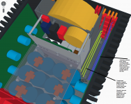
Distance is the key to preventing magnetic coupling. I would not run input and output wiring next to each other. If the twisting is tight enough you might get away wth it. Try to ensure that the pairs have different twist lengths from each other - if two pairs have the same twist then it is as though they are untwisted.
I would not run input and output wiring next to each other.
Please describe or modify the diagram to how you would run the cables as I can't see any other way of getting more distance when the connectors are panel mounted next to each other? The are already divided by a steel plate.
By "twist lengths" do you mean the "tightness" of the twist?
Should I use horizontal steel partitions as well on that plate (unless you have an idea where that plate is no longer there) ?
Thanks
Last edited:
I would not have mounted the input and output connectors so close together.
Strictly speaking, twist tightness refers to how close the two wires are to each other but people often use it to mean twist length instead.
I think you need to get away from your obsession with adding steel plate everywhere to solve layout problems. Steel does not shield magnetic fields in the way that any good conductor will shield electric fields.
I would not have mounted the input and output connectors so close together.
There is nothing I can do to solve this, I either have them there or next to the AC IEC inlets on the other side. The transformer takes up most of the space on the back panel and it is too large to sit in the middle above the caps. I can't extend the panel any wider without violating max rack mount width which I want to maintain.
Given the locations of the output and input are therefore fixed, what is the best strategy for minimising coupling based on my suggestions or any other ideas?
Most of the other steel panels are for structure support btw.
Thanks
- Status
- Not open for further replies.
- Home
- Amplifiers
- Solid State
- 6-channel-amplifier-grounding